This blog is intended to give a brief and general overview of how to adequately perform in-vivo footplate experiments by using Aurora Scientific equipment with most murine models. This technique can be applied to small or large rodents, and even larger mammals such as rabbits, dogs and pigs. This blog is meant to act as a quick start guide for to illustrate some general principles of the in vivo method, therefore, the following steps will be kept to an overview and will showcase the most basic tools necessary to carry out the experiment.
For more detailed procedures and resources for these types of experiments please follow the links below to your preferred format:
Now, let’s get started!
Basic tools that you may need:
1. 1300A/1305A Whole Animal System
2. anesthetic for IP injection or an anesthesia machine (isoflurane)
3. a heating lamp or water circulator
4. adhesive tape
5. electric shaver or hair removal cream
6. forceps
Step 1:
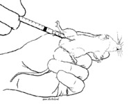
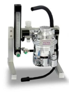
To anesthetize the animal, you could choose to use IP injectable anesthesia such as ketamine-xylazine, or more commonly, provide an inhalable anesthesia such as isofluorane with an anesthesia vapourizer. Isofluorane is by far the most common anesthesia used in this procedure as the animal goes under quickly and it is used to maintain anesthesia throughout the experiment. As many researchers us the in-vivo technique as a survival study, isofluorane is also preferred as the animal will recover from its effects quite quickly and can be anesthetized again some time later for the next end point in the study. Before proceeding with the experiment, it is essential to confirm that the animal is sufficiently anesthetized by the lack of a deep tendon reflex (no foot or paw withdrawal in response to pinching). You may need to use forceps to check this adequately.
Step 2:
Completely remove all hair on the lateral side between the ankle and pelvis of the leg which will undergo the procedure by using an electric hair shaver. Hair removal cream such as Nair may be used as a substitute. Proper hair removal is essential for landmarking the electrodes and obtaining a good clamp of the knee joint. You may optionally clean the shaved area with betadine and 70% alcohol to prevent bacterial infection from occurring.
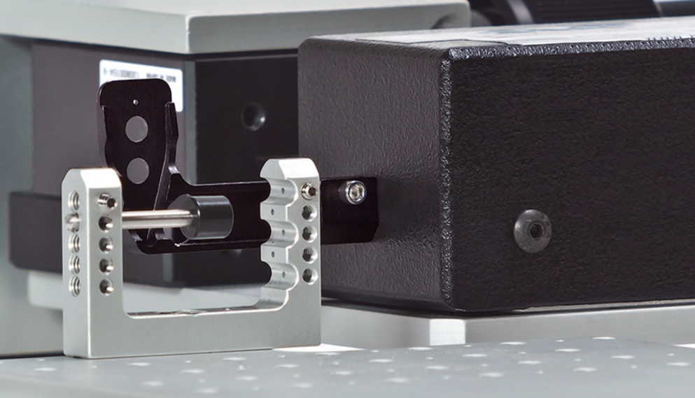
Step 3:
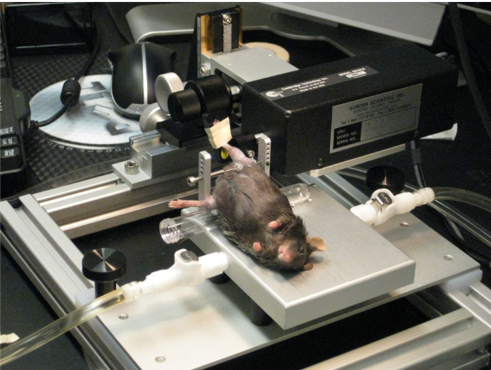
Prepare the apparatus (809C for mice; 806D for rats) of the 1300A/1305A system by affixing the knee clamp to the animal/limb platform and place the animal in the supine position. If you are using isofluorane, then ensure the nose of the animal is securely in the nose cone so it remains at a sufficient depth of anesthesia. You may need to secure the nose cone to the plate with some tape. Now we can begin to secure the animal in the apparatus. Secure the leg by using one of our U-shaped knee clamps. The clamp will be most effective with the pad positioned slightly distal to the patella on a fleshy portion of the upper compartment of the limb. Ensure proper stabilization by pulling and pushing on the lower leg, any compliance in this area will affect torque measurements later on. Once the leg is secure, place the animal’s foot in the footplate attached to the dual-mode motor with the heel set in the groove and the toes firmly planted. Secure the foot to the pedal by using some thin strips of adhesive tape. Use more than one strip and attempt to tape around the ankle and toes of the animal. During this step you will find it helpful to keep the foot pressed against the pedal by holding it in place with the forceps whilst applying the tape.
Step 4:
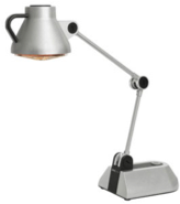
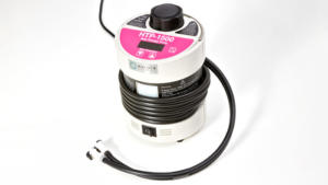
At this point if you have not turned on your heating lamp or circulator, you must remember to do it now. Failure to do so may result in the animal being unable to maintain its normal body temperature which will greatly affect normal physiological function. If the animal is cold, this will affect the contractile torque measured (greatly reduced) and may even result in the animal being removed from the study.
Step 5:
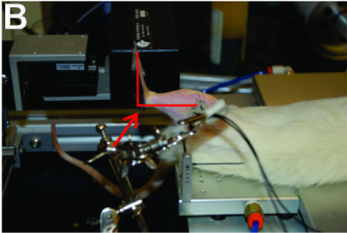
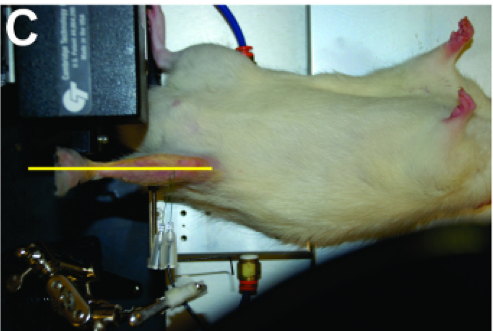
Adjust the position of the leg and the foot by using the micro-positioners mounted to the apparatus which control the position of the dual-mode lever system. The foot should be aligned orthogonally to the tibia at 90°. You should also adjust the position of the leg relative to the body of the animal by adjusting the x-axis of the micro-positioner. Adjust its position until you are able to ensure there is a straight line from the point of the knee to the point of foot pedal when you look at the leg from a side and bird’s eye view as shown in the photos above.
Step 6:
Place both needle electrodes subcutaneously near the peroneal nerve if you plan to measure dorsiflexion (TA/EDL) or near the Tibial nerve for plantarflexion (Gastrocnemius/Soleus). For direct muscle stimulation (to remove nerve or NMJ effects) vertically place the electrodes subcutaneously near the mid-belly of anterior compartment of the leg for dorsiflexion or the posterior compartment for plantarflexion. This is the most challenging part of the procedure as it requires some ability to landmark accurately without actually being able to observe the nerve/muscle. Complicating matters is the fact that in order to make a good measurement of torque, it is essential to avoid stimulating the antagonistic group of muscles (co-contraction). There are a few strategies to avoid co-contraction and will help with making a consistent measurement.
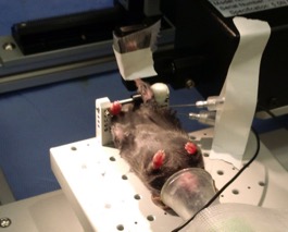
1) Do not place the needles too deeply subcutaneous: It is a good idea to use forceps to pull up the skin from the target area and gently slightly insert the tip of the needle electrodes into this patch of skin. The elasticity of the skin will pull the electrodes down when you release the forceps. You can also use some helping hand clamps to hold the electrodes in place. 2) Place the points of the electrodes close together: This means that the current will take a shorter path between the two electrodes and there is less chance of activating any undesired nerves or muscle tissue. This will also reduce the amount of current required to fully activate the muscle. 3) You can place one electrode subcutaneously and then prod trans-cutaneously with the other. This will help with the landmarking of the electrodes and will help minimize re-positioning. Note that this will only work with the stimulator actively running. For more details about placement of electrodes please review the SOP or our sponsored JoVE videos on website.
Step 7:
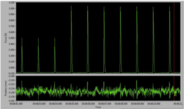
With the electrodes in position, open the live data monitor in the DMC software to track test twitch contractions in real-time. You can use the software function “InstantStim” in the DMC program to continuously trigger twitch pulses from the stimulator without the need to record a data file. Begin with the “RANGE” knob set to 10mA and the “% ADJUST” set to 0.5 on your stimulator. By adjusting the magnitude of the stimulators current (turn the “% ADJUST” knob on the front panel of stimulator), you can find out the optimal stimulation current. You may need to change of placement of the electrodes if the spikes look abnormal or there is evidence of co-contraction. The optimal stimulation is the current at which you observe the greatest torque production which remains constant. If you elicit too much current from the stimulator then you will likely activate the antagonistic muscles of the leg, which will result in co-contraction and poor/reduced torque measurements. Thus, the optimum amount of current required looks like a bell curve. Too little will not fire the muscles adequately, too much and the force drops because of the contribution from the antagonistic group.
Step 8:
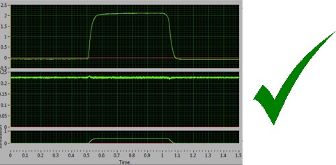
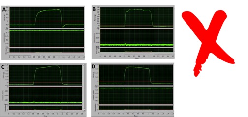
You are now ready to carry out a real protocol and experiment such as an isometric tetanic contraction, which is shown above. Any peculiar data or contractility could be generated from improper manipulations in previous steps and generally comes down to misalignment of the leg, insufficient stabilization of the knee, improper security of the foot and placement of the electrodes (position or stability). Please review and for any persistent issues please contact Aurora Scientific if you have problems and questions about the in-vivo method.For a primer on writing numerous types of protocols, please read our blogs linked below.
How to Write Basic Protocols in DMC – Isometric
How to Write Basic Protocols in DMC – Concentric and Eccentric
How to Write Basic Protocols in DMC – Isotonic