In one form or another, pain has affected everyone at various points of their lives. Effectively managing pain is a difficult task as it can be highly subjective, and tolerance can vary widely. Although an immense amount of research has been done, more is required to better understand the cause of chronic and acute pain and more effective treatments for it.
When it comes to pain research, there are numerous ways to assess the nociceptive response in animal models as well as humans. Mechanosensitivity, for instance, has been studied for many years to identify causes and treatments for allodynia, a pain response to a non-painful stimuli or hyperalgesia, which is an increased response to a normal pain threshold. This can be measured by applying a stimulus, whether painful or non-painful and measuring the animal’s response with a paw withdrawal, for example. Another example to consider is the study of receptive fields, which is an area innervated by free nerve endings of a single nociceptor or mechanoreceptor that responds to mechanical stimuli. These can be mapped out by varying the location of noxious stimuli and recording the receptor activity in response. More recently, vibrotactile sensing in patients suffering from neurodegenerative diseases has been studied to measure a participant’s altered sensitivity or reflex response to high frequency sinusoidal stimuli.
In this blog, we will briefly discuss the types of experiments than can be performed with our 300C-I mechanical stimulator to elucidate the mechanisms behind these common experiments performed. For the protocols outlined below, control of the mechanical stimulator will be done with Aurora Scientific’s DMC software.
Indentation Distance
The first type of experiment or protocol we will look at is performing precise indentation by controlling the depth of mechanical stimuli. Here, we will command the motor to indent a defined distance over a set duration and then released. You can then vary the depth of stimulation to look at tissue sensitivity, material stiffness or other deformation properties.
It is important to note that when setting up the motor, the orientation of the indenter arm will determine the direction of stimuli being applied. For example, if the indenter arm moves in a clockwise direction, length and force application would be positive, whereas counter-clockwise would indicate a negative length and force application. From here onwards, the mechanical stimulator is oriented so the indenter arm moves in a counter-clockwise direction and thus length applications are negative.
In DMC, there are two ways to produce a length control stimulus. The first would be to apply a length step, i.e. controlling the indentation distance and applying it as quickly as the motor will allow. In the example below (Figure 1), we want to control the rate of indentation and thus we use a ramp where you can define the indentation distance as well as the velocity. Here, we are indenting 4mm (note the -4 circled in red) and the time is 0.1s. Thus, the indenter arm will move 4mm into the membrane 4mm in 0.1s, hold for 5s as shown in the ‘wait’ time on line 2, and returned to 0 mm in 0.1s once again.
To modify the distance moved, you simply need to change the ‘-4’ to a number of your choice depending on your application (ex. 1mm, 2mm, etc.)
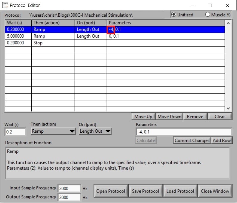
Figure 1. Screenshot of Protocol Editor in DMC showing the defined parameters for a controlled length stimulus.
In Figure 2A, you can see the mechanical stimulator applying force to the membrane by indenting it 4mm, holding for 5s then releasing. The resultant force and length profiles from this stimulus can be seen in Figure 2B.
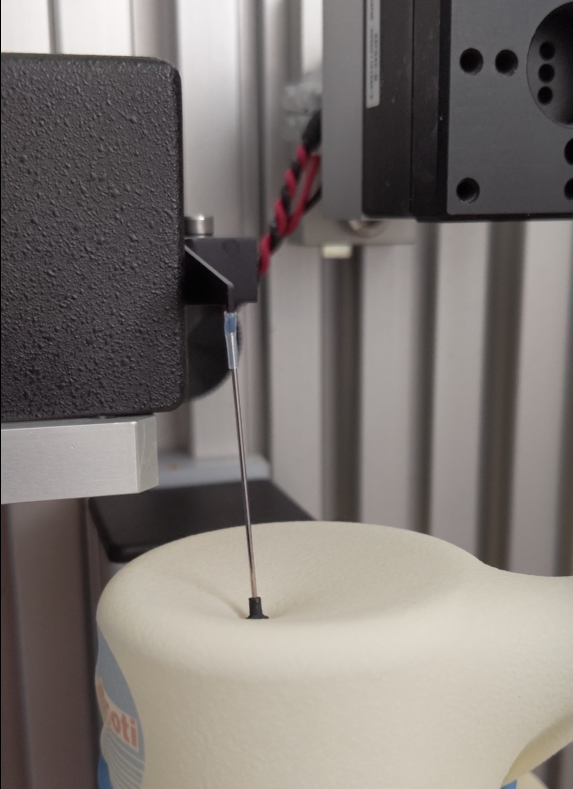
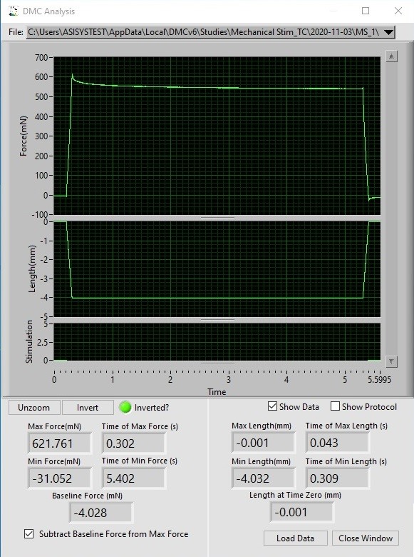
Figure 2. (A) Mechanical stimulator mounted on an apparatus to apply stimuli to a mock membrane. (B) Software display of resultant length and force profiles following execution of the protocol.
Vibrotactile Stimulation
Another experiment we can perform is vibrotactile stimulation. In this setup, you can execute sinusoidal stimulation of a hand, foot, or other tissue at varying frequencies and amplitudes and measure the corresponding response from a subject, tissue or receptor.
In order to execute this type of stimulus, you’ll need to generate a sinusoid with the mechanical stimulator which requires definition of the frequency, amplitude (peak to peak) and number of cycles. You can then utilize this blueprint to adjust the frequency of these sinusoids from 25Hz (Figure 3; Red circle) to higher values of your choosing. Once the frequency is selected, you can determine the amount of time you wish the stimulus to be executed for which will define the number of cycles (Figure 3; Yellow circle) required at said frequency.

Figure 3. Screenshot of Protocol Editor in DMC showing the defined parameters for a typical vibrotactile stimulation.
As you can see in Figure 4A, the mechanical stimulator is executing a vibrotactile stimulus at 25Hz with an amplitude of 1mm (+/- 0.5mm) over a period of 5s. The resultant sinusoid profiles are shown in in Figure 4B and 4C.

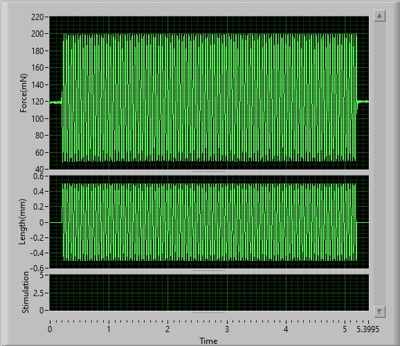
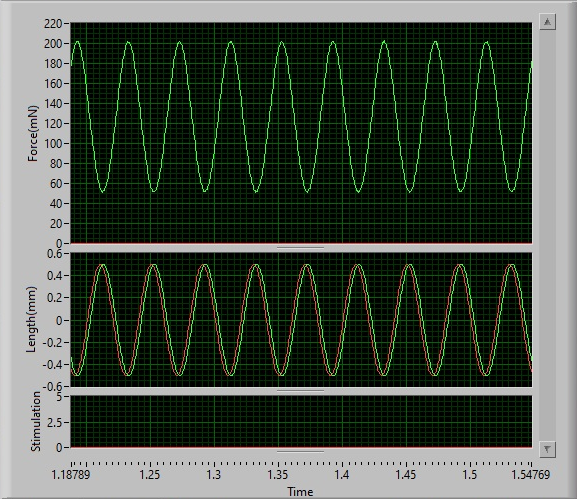
Figure 4. (A) Mechanical stimulator mounted on an apparatus to apply vibrotactile stimuli to a mock membrane. (B) Software display of resultant length and force profiles following execution of the sinusoid. (C) Zoomed in view of the sinusoidal stimulus at 25Hz.
This type of protocol can also be programmed to vary force sinusoidally, which brings us to our final experiment type, Force Hold.
Force Hold
In our final and most common experiment, we will look at applying a constant force (mN) or pressure (kPa; mN/mm2) to model mechanical stimulation of a nociceptor’s receptive field. Here, we can vary load (i.e. 250mN to 400mN), application area (ex. 0.3mm to 3.0mm), velocity and duration of stimulation to measure things like firing rate of nociceptors.
Unlike the above experiments, the force hold is executed by controlling the amount of force applied to the membrane or tissue. In order to do this, you will need to orient the indenter arm on the motor so that it is moving clockwise (positive force and length), or by using a force reversal cable (like the example below). Furthermore, the control system of the mechanical stimulator requires the force offset dial to be set to ‘0’ putting it into force control mode. Once this is set, ensure the indenter arm or extension rod and tip are lightly touching the membrane or tissue prior to executing any force application.
Taking a look at Figure 5, the protocol is slightly more complicated than previous two as the dual-mode indenter requires a length command and force command in order to execute a constant load experiment. The first line indicates a length movement larger than what is required to reach the force that is going to be applied, in this case it is defined as 5mm but is often less depending on the tissue being stimulated. Since the unit is in force control mode, it will not execute a length command until a force command is initiated which line 2 of the protocol indicates. Here, a force hold of 250mN is being executed in 0.3s, held for 0.4s and released back to 0mN in 0.3s (line 3). Once the force hold is executed, another length command is required to move the indenter arm back to its initial position (line 4). For subsequent force holds the value in line 2 (circled in red) is the only one required to be changed (i.e. to 300mN, 350mN, etc.), unless the length required to reach higher forces is greater than the length defined here. In which case, the value in line 1 (5mm) will also need to be changed.
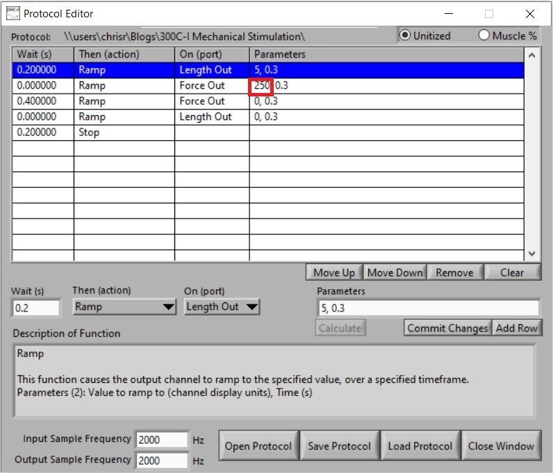
Figure 5. Screenshot of Protocol Editor in DMC showing the defined parameters for a constant force stimulation experiment.
If you compare a constant force stimulus with a constant length stimulus they look quite similar (Figure 2A and 6A), however the resultant profiles differ, specifically on the force channel in Figure 6A which shows accurate and controlled application of force at the defined velocity and duration (Figure 6B).

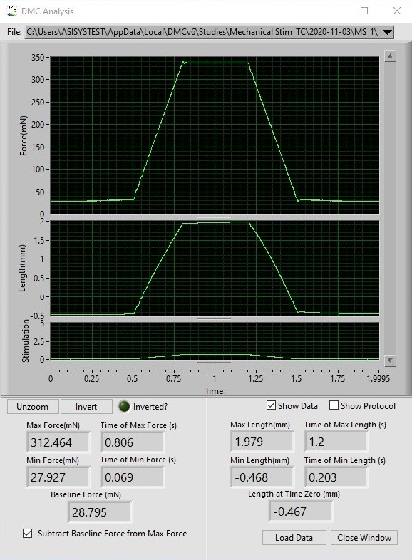
Figure 6. (A) Mechanical stimulator mounted on an apparatus to apply force controlled stimuli to the membrane. (B) Software display of resultant length and force profiles following execution of the protocol.
If you would like more information on our mechanical stimulator, check out our latest Tech Cast or for more detailed insight into your application or needs please contact us at info@aurorascientific.com
Stay tuned to this blog for more upcoming tips and tricks on a wide variety of products and topics!