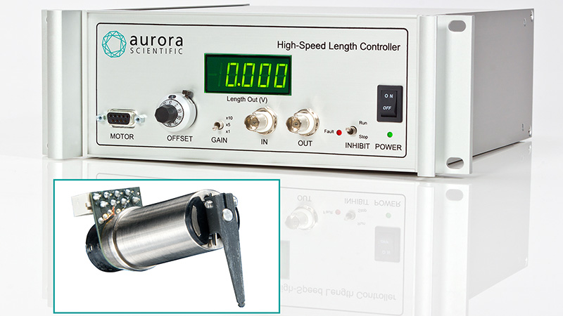
Our 315D & 322D models of High-Speed Length Controllers are routinely used by researchers studying small tissue samples such as fibers and cells because these instruments offer very high positioning accuracy (better than 1um) with a very fast response time. However, to leverage the usefulness of this positioning accuracy we must calibrate these length controllers precisely.
Recently, we published a blog which details how to calibrate our Dual-Mode Lever Systems. To measure changes in length with the Dual-Mode we mark a piece of paper or tape and measure the length change with a vernier caliper. However, the High-Speed Length Controllers are much smaller than the lever system motors and much more difficult to mount in this way. Additionally not all models have a hole in the tip of the arm and thus it is hard to make the marks as accurately. What we require is an optical method of calibrating these smaller motors. Fortunately, such a method exists.
Many of our high-speed length controllers are sold as part of our 1400A or 1600A systems. These systems are all equipped with our High-Speed Video Sarcomere Length program or HVSL for short (link). When the length controller is mounted as part of the system onto your inverted microscope, we can use the ‘markers’ function in the HVSL software to accurately measure the displacement of the length controller or its hook attachment.
Begin by preparing your length controller and system for experiments. If you have not yet calibrated your HVSL system to your microscopes objectives you should do so now before proceeding. Please find a video tutorial here.
When ready to calibrate the length controller start by focusing on the tip of the lever arm or the attachment hook as shown in Figure 1. The ‘markers’ function is under the tab labelled tools in the HVSL program.

Figure 1: 200um minutien pin mounted to 322D under 4x magnification.
At this point we set our defining marker at this home, or zero position. Before beginning, ensure that the length controller is not offset and is centered at its zero position. It is important to consider whether we will be calibrating in both the negative and positive directions as this will dictate which marker we should make the defining marker. In this case we will only calibrate in one direction and thus, it will be marker 1. At this point we can click the +Add button for marker 1 and place it at the very tip of the hook. (Figure 2). Take care to place this in the center of the hook for best results.

Figure 2: Marker 1 placed in center of the hook.
We should now proceed to apply a known voltage to length controller to induce a movement which will be easily observable by the HVSL program. The voltage may be applied through our 600A length calibration applet or may be achieved by simply turning the length offset knob on the length controllers’ electronics to the desired voltage. Place a marker at each position and repeat as many times as desired (Figure 3).

Figure 3: Series of markers placed at each movement point.
Once all the markers have been placed you can directly export the distance values to the ASI 600A program if you are using the program’s length calibration wizard (Figure 4). This program will then plot a linear regression for the data points supplied by the HVSL program.

Figure 4: Marker points exported to 600A calibration editor window.