Here we will cover some of the more common issues that researchers encounter when using our Dual-Mode Lever System. If you encounter an issue with your device, please do not hesitate to get in touch with any member of our team and they will be more than happy to hear about your issue and troubleshoot it accordingly.
My motor is faulting
If the motor of your dual-mode lever system is faulting (i.e. kicking back and forth with fault light on; see Figure 1) there could be several things causing this.
Simpler/quicker items to check first would be:
- Is the motor cable connected properly between the dual-mode lever control box and the motor’s connector. Loose mating here would cause the unit to fault
- Disconnect BNC cables from the front panel of the control box to ensure the fault is not being caused by an inappropriate signal from your software or DAQ system
- Ensure that the motor model you are using matches the controller it is plugged into. i.e. make sure you have not plugged a 305C motor into a 300C controller or vice-versa
- Check, and let us know the serial number of your device, so that we can confirm the model type. As with all companies, over the years we have brought out new models of this device in which we have fixed some of the common issues experienced by our clients with prior models

Figure 1. Fault light illuminated on 300C Series Dual-Mode Lever System
The length and force offset dials on the control box determine the angular position of the lever arm/footplate (length offset) and the amount of holding force on the unit (force offset). Incorrectly using these dials is another frequent cause of motor faulting.
- these should normally be set to 5 (length offset) and 10 (force offset) respectively for an isometric measurement. All tuning and diagnostics should be done with the dials at these values
- if the length offset is set at one end of the spectrum, say 1 or 9, the unit may be too close to the outer edge of its range and thus cause faulting
- It is important to ensure that the unit’s force offset is at 10 (isometric to 100% of maximum). If this is set to a low value like 0 or 1, it is possible the unit is faulting due to lack of holding current on the motor
- change these offsets to 5 and 10 to determine if this is the cause
If neither of these reveals the issue, another potential cause could be that the position detector of the unit is malfunctioning (either in the motor, or in the circuit). In order to determine whether the position detector is the root cause of the issue you are experiencing:
- turn the unit on and flip the inhibit switch to ‘stop.’
- move the lever arm or footplate through its entire range of motion (full CCW to full CW) and note the voltage display on the length channel
- this should read at least +/- 10V (likely 13 or 14) if still intact
- if it does not, then the position detector of the motor or circuit is faulty and needs to be sent back to the factory for evaluation and possible replacement
Rarely but in some cases, a heavy load or tight wire in the end of the lever arm can cause persistent faulting.
- if you have changed the lever arm, or if you have added some extra weight to the end of your ASI lever arm (hook, clip, etc), remove this added weight and see if its removal rectifies the issue you have been experiencing
- if the unit works fine once the load is removed then it’s likely that the load is too much OR the unit needs to be re-tuned with the new weight (i.e. slowed down due to the inertia). Retune your unit by following the instructions outlined in section 6.0 of the 300C, 305C, 310C Dual Mode Muscle Lever Manual (page 12)
If none of these elucidate the issue, then I would suggest plugging another motor head (same model of course – 305C for a 305C, or a 300C for a 300C) into the controller. This will allow us to identify if the issue lies within the motor itself, or the controller. If the motor is the issue it’s likely based on the above that it is broken (butterfly, magnet, etc.) and needs to be replaced. If it is in the controller, then it will need to come back for evaluation.
I understand that many of you will not have a second unit to be able to carry out this test, so in this case, we would suggest sending back the entire device for our specialist team to have a look at.
The lever arm/footplate is oscillating or making a high-pitched noise
Oscillations tend to be caused by uncontrollable load or an unstable motor. The most common causes are:
- the lever arm/footplate not being clamped properly onto the motor shaft (see figure 2)
- worn/stripped arm/footplate due to heavy or incorrect use, but potentially also due to a manufacturer’s defect
As I previously touched upon in the previous section regarding motor faulting – if the unit is subjected to a non-compliant load like metal or the wire in the hole of the arm it will oscillate violently. Therefore, again, it may be worth:
- checking whether the oscillations remain after removing the new lever arm/additional load
If they do, now you know that the new lever arm/additional load is too heavy and is causing the observed oscillations. Replace the lever arm or reduce the load on the lever arm to resolve the issue. Should the situation not resolve, then it is possible the lever arm is clamped improperly on the motor shaft, usually it is mounted in a way that the lever arm is touching the case of the motor (see Figure 2). This almost always manifests itself as an oscillation or increase in noise on the force and length channel, but in some cases, an improperly mounted lever arm can lead to persistent faulting. To resolve this, mount the lever arm onto the shaft taking care to leave a gap between the arm and the motor case to prevent rubbing.
Oscillations may also be the result of working with a motor that is not tuned properly (i.e. control loop too fast for inertial load). Similar to above, retuning your unit by following the instructions outlined in section 6.0 of the 300C, 305C, 310C Dual Mode Muscle Lever Manual (page 12) would alleviate this problem.
Another potential source of oscillation could be that the wrong motor is connected. In this situation the motor would normally oscillate violently prior to being stuck in a fault condition. If you accidentally plug a 305C motor into a 300C controller, or vice-versa, this will lead to oscillations which if not immediately addressed will almost always damage the motor beyond repair.
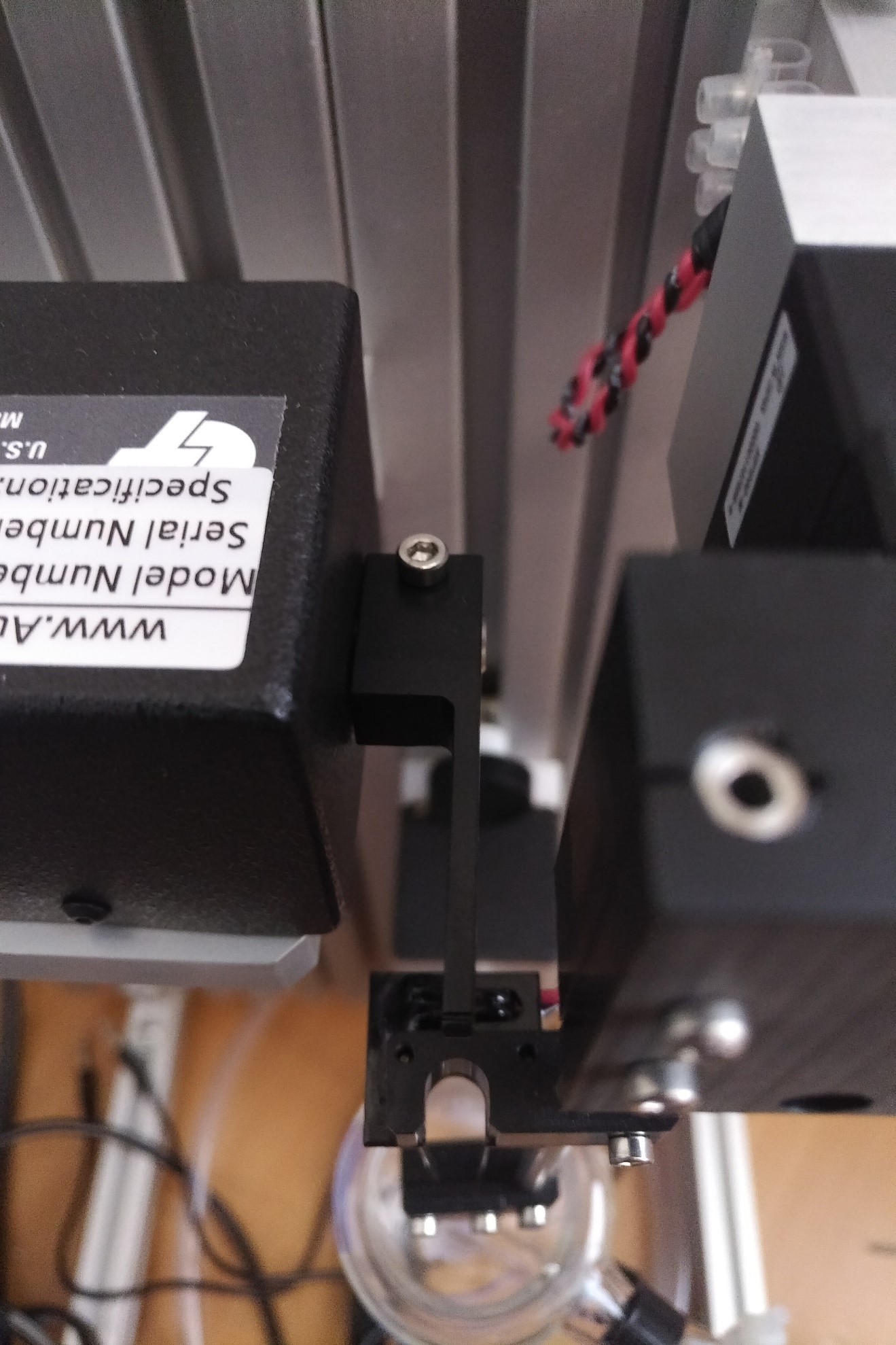
Figure 2. Improperly attached lever arm, touching the motor casing and not tightened up properly
There does not appear to be any force being measured; displays are not changing
If there is no force being recorded by the unit, make sure the inhibit switch on the controller is in the run position.
- If it is set to stop it will not record anything, and the baseline force profile will look like a 60Hz square wave when viewed in software
- If it is in run, then check to see if the force offset dial is at 10. If the unit is at 0 then it is likely there will be no force recorded without a force control command in the software.
If neither of these apply, check to see if there is a voltage change on the force display of the controller when you press on the lever arm/footplate. If not, ensure the black and grey motor cable is connected properly as per above. If that’s not the case then it is possible the motor is broken. To check this, substitute a second motor of the same type (if possible) and if the problem is not resolved then the motor is likely broken.
You can also check the motor fuse which is located inside the controller. The fuse cartridge can be removed from the holder and tested for continuity with a voltmeter.
Should the voltage change on the controller but not on the software (blank force/length displays, a flat line on the live data monitor or empty data files) then the dual-mode lever is likely working but there may be some issue with the connection to the software or with the software itself.
No force or length traces generally means that the software is not communicating properly with the DAQ or the instrument itself. In order to troubleshoot this:
- open File → live data monitor
- tap the dual-mode lever arm or footplate to see if there is any change in force
- if you observe a change in force on the live data monitor, then the lack of force on your trace is likely resulting from no stimulation, or your muscle is not viable. (please go to the end of the page for more information on how to troubleshoot an issue like this)
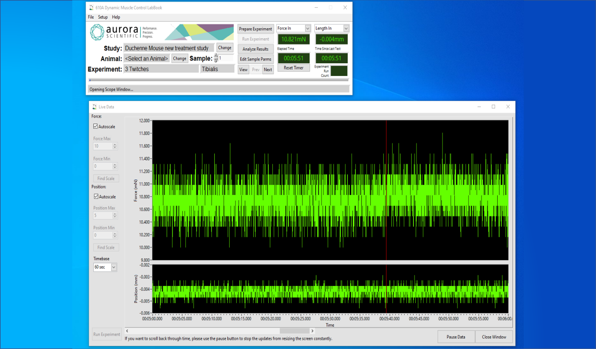
- If there is no force change on the live data monitor and the channel displays in the main window of DMC are blank, (see Figure 3) ensure that the proper instrument and channel setup has been done. Open Setup → My Instruments to confirm you have added the correct instrument. If so, open Setup → channel setup and confirm that the instrument you’re using has been set as your Length In/Out and Force In/Out device (in the case of a Dual-Mode)
The 300C Dual-Mode Muscle Lever communicates with DMC via the signal interface and some form of A/D card or integrated USB box so if there is no force change from the above steps you should inspect these closer:
- check that the BNC connections are made correctly between the 300C Dual-Mode Muscle Lever and the 604A or associated interface.
- ensure the ribbon cable or USB cable connecting the interface to the PC or laptop is connected properly
- If you have a PCI card, check to see if this is seated properly in the slot, or move it to another slot if available.
If the connections have been made correctly, and the issue still persists, please follow the instructions:
- locate and open the NI Max program on your PC
- click on devices and interfaces on the main screen (the model of the DAQ you are using should be listed here, there should be an icon that is green showing it is working)
If there are multiple devices on there (i.e., Dev 1, Dev 2) and only one is working then it is likely that there was a second device accidentally installed by Windows and DMC is communicating with the wrong one.
- go to DMC → File → Open Log Folder and delete the file DAQdevice.ddv
- reopen DMC, select the device that is working (i.e. Dev 2), then ‘remember my selection’ and OK.
- check to see if the communication is now restored via live data monitor.
This can more commonly occur when frequently connecting and disconnecting a USB DAQ device or after a Windows update.
If there is a single device present and it is not communicating properly then double check the PCI card and reseat it in the slot. Following the above step may result in a second device being created. In the off chance that it does, follow the steps above.

Figure 3. No communication between software and the lever system
My muscle isn’t contracting/no force showing/nothing coming out of stimulator
You only need to look at the following information if you are not observing any change in the force/length on the live data monitor and by applying pressure to the lever arm of your 300C you observe a response on the live data monitor. The above suggests that the issue lies within the 701C stimulator. (see figure 4)

Figure 4: DMC Software showing a normal noise profile from a lever system
In order to initiate troubleshooting your stimulator:
- check that the LED pulses light blinks when the unit has the output switch set to ‘ON,’ range dial set to something other than off and the adjust dial greater than 0
- press the manual trigger button
- if the pulse light blinks, then it is likely the unit is outputting some current or voltage
- to measure this value, you will need to fabricate a resistor attachment across the output pulses BNC (voltage mode requires a 10kohm resistor, current mode a high wattage, 5W min, 10ohm resistor). See Figure 5.
- the above are required because directly measuring output voltage on a scope or computer will likely break them due to the amount coming out of the stimulator or produce an erroneous result
- set the output to something low like 1V and using an oscilloscope or our software, observe the voltage coming out using a protocol with a longer duration (i.e. 1-2s) and then slowly increase the output voltage to see if it follows as it should
- if the software does work as it should, then the unit is working.
- this can also be checked through the voltage and current monitors, but these are somewhat more finicky to use.
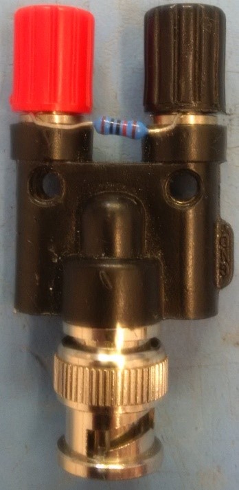
Figure 5. A 10kOhm resistor tied around the output of a BNC to screw terminal adaptor to measure output from 701C stimulator.
If the output does not follow, then there could be an issue with the circuitry on the board that regulates output via the adjust dial or the adjust pot is malfunctioning. This unit would need to be sent back to us for our specialist to investigate.
Another cause for no force is that the unit is overheating due to continual use and thus the FET(s) inside the box is temporarily shut off with the internal thermal regulation circuit. Open the box, allow it to cool and try again the next day to see if the unit is working normally. If not, toggle the pulses switch to negative, positive and bi-phase to see if the output changes at all. It is possible one or both FETs are blown if the output varies or does not happen in these positions. If this is the case, they will need to be replaced by our technician.