Do you require visualisation of your sample during measurements?
Aurora Scientific provides several systems that can be mounted on an inverted or confocal microscope for visualisation of the muscle sample, sarcomere measurement and/or fluorescent measurements.
Three of our products have been designed for easy mounting on an inverted microscope; The 801C small intact muscle apparatus, the 802D permeabilized fibre apparatus and the 803B skinned myocyte apparatus. For all three the following features are recommended in a microscope:
a) Side port C mount for attachment of a sarcomere measurement camera or laser diode
b) A Flat, Three-Plate, XY stage for positioning of the apparatus with a minimum cut-out size of 100mm
c) Retractable condenser for extra working space when mounting a sample
d) Long range working objectives
Each product also has some specific requirements:
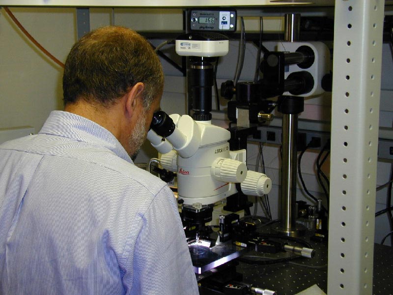
1) The 801C apparatus of our small intact muscle test system
The 801C small intact muscle test apparatus has been designed to minimize the distance between the objective and the muscle tissue. As a consequence the force transducer housing protrudes below the level of the bottom of the 801C mounting plate and thus the microscope stage. The microscope stage must therefore have a minimum centre cut-out which measures 100mm diameter. This cut-out is required for clearance of the bottom of the force transducer. The 801C is supplied with a bench stand. The apparatus should be stored on this stand when not in use and when it is used with a dissection microscope.
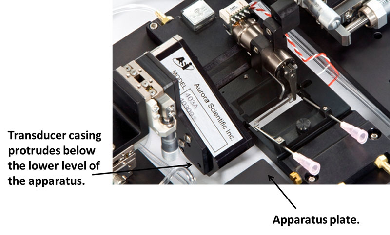
Figure 1. 801C small intact muscle apparatus.
2) The 802D apparatus of our permeabilised fibre test system
The 802D permeabilised fibre apparatus is also supplied with a bench stand. The apparatus should always be stored on this stand when not in use and when it is used with a dissection microscope. Like the 801C the force transducer protrudes below the lower level of the 802D. Additionally when the bath plate lowers it moves below the lower level of the apparatus. Therefore the microscope stage must have a minimum centre cut-out which measures 100mm diameter. This cut-out is required for clearance of the bottom of the force transducer and for clearance of the bath plate when it lowers and moves. When the apparatus is not on an inverted microscope, it must be stored on its stand and not allowed to rest on the force transducer or the bath plate.
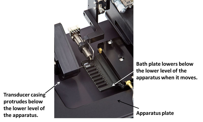
Figure 2. 802D permeabilised fibre apparatus
The alignment of the apparatus on the microscope stage is critical to ensure that the moving bath plate doesn’t contact the cut-out on the stage. To allow the researcher to easily remove and replace the apparatus on the stage we include alignment blocks with the product. These blocks have double-sided tape on the bottom to facilitate easy attachment to the microscope stage. First align the apparatus on the microscope stage, operate the 802D through its entire range of motion and check that there is no interference. When you are sure that the apparatus is aligned properly then attach the alignment blocks to the stage so that they are touching the edges of the apparatus plate on all four sides. Now when you place the apparatus within the blocks you will be assured that the alignment is perfect every time.
For further information about setting up an 802D on a microscope please have a look at the following video
Fig 5. 802D permeabilised fibre apparatus on microscope stage with alignment blocks (silver)
3) The 803B apparatus of our skinned myocyte test system
The skinned myocyte test apparatus attaches to the XY translation stage of the microscope by simply fixing the apparatus to the centre portion of the stage. Long working range objectives are essential because the myocyte is located above the top surface of the plate and the plate is 3mm thick. A stage capable of XY movement is also essential because the plate must be translated from one well to another in order to change the pCa concentration. A vibration isolation table is required to isolate our extremely sensitive force transducer from vibrations present in all labs. The apparatus includes two boom mounts and two motorized XYZ translation stages. The motorized XYZ stages must be mounted to the boom mounts which are in turn mounted to the vibration isolation table on either side of the microscope.
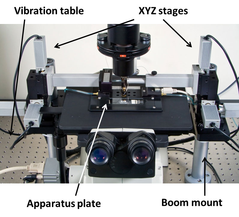
Figure 4. 803B skinned myocyte apparatus
Mounting the tissue
With both the 801C and the 802D apparatus the tissue is mounted on the apparatus using a stereo microscope. Most labs arrange their equipment in one of the following two ways:
1) Stereo microscope is located beside the inverted microscope. With this arrangement the two microscopes are located beside each other with the bench stand located under the stereo microscope and the alignment blocks attached to the inverted microscope stage. The electronics and other ancillary equipment are positioned so that it is easy to lift the apparatus off the bench stand and place it on the inverted microscope stage after the tissue is attached. With careful layout of the microscopes, the required electronics and ancillary equipment allow this move to be accomplished with minimal chance of damaging the equipment or the preparation.
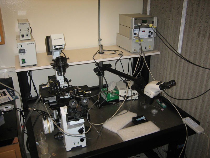
Figure 4 Equipment Arrangement with Stereo and Inverted Microscopes Side by Side
2) Stereo microscope is mounted to a boom arm that can be swung into place above the inverted microscope stage and then the tissue attachment is done while the apparatus is mounted on the inverted stage. With this arrangement there is no moving of the apparatus and therefore there is less chance of damaging the equipment or the preparation. However mounting the tissue can be more difficult since the researcher has to work on top of the inverted microscope stage, which can be more awkward.
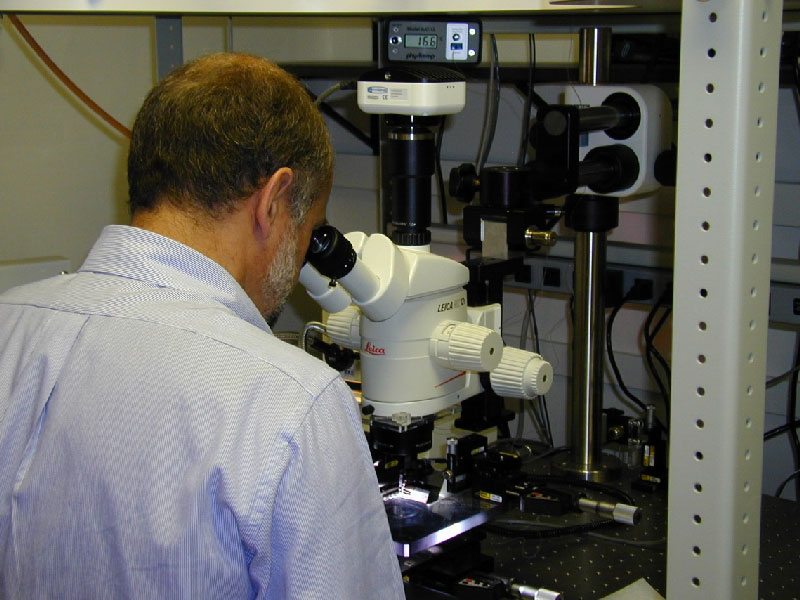
Figure 5 Stereo Microscope Mounted on Boom Arm.
In choosing a stereo microscope, ensure that there is enough throat distance – the distance between the support pillar and the area of observation. Many stereo microscopes have a small throat distance which can’t fit the 801C or 802D underneath the observation area because the apparatus hits the support pillar.
If you have any questions regarding the choice of a suitable microscope please do not hesitate to contact us.
Follow our blog, or follow us on Facebook and Twitter for further tips and news from ASI!