The Force & SL Control window provides an interface for controlling the software
feedback control system built into the 600A program. This feedback control system allows the
program to control force or sarcomere length using length changes imposed on the tissue by the length controller. Since every tissue has different properties and characteristics; this control panel allows the user to tune the settings to optimize feedback control for each individual experiment.
We will first of all deal with Force Control as it is more widely used than SL control.
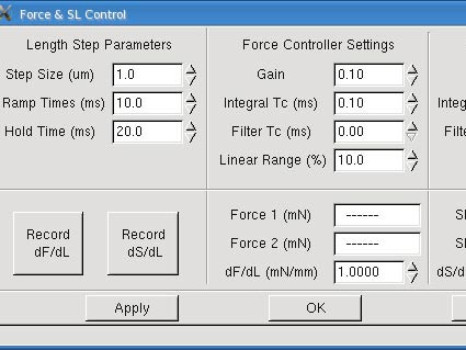
The Calibrate→ Force & SL Control menu item opens the Force & SL Control Window. This window is used to calibrate and tune the force control and sarcomere length feedback control functions of the 600A program.
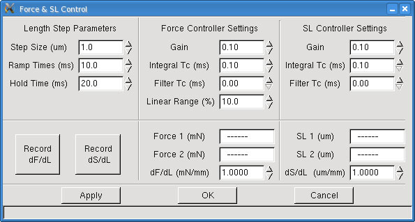
Fig 1. Force and SL Control Panel of the 600A Digital Controller
Note: Since every tissue has different properties and characteristics; this control panel allows the user to tune the settings to optimize feedback control for each individual experiment. The Force & SL Control window is not used with Dual Mode Length Controllers (300C, 305C, 309C, 310C) because these instruments have force control built into their electronics.
A feedback control loop is necessary when you want to change a parameter that is not directly controlled. In this case, we want to change the force by adjusting the overall length of the tissue. In the program we call this dF/dL (change in force for a unit change in length), or stiffness. The stiffness is determined by imposing a known length change on the preparation and measuring the resultant change in force.
In order to determine the stiffness (dF/dL) of a tissue sample, a known length change is imposed on the tissue and the resultant force change is measured. The stiffness is the amount of force change per mm of change in the tissue length. This value is required for a feedback control to work. If you want to hold the force constant at a certain value, and it is not at that desired value, then the program must be able to determine how much to move the length controller to achieve the desired force.
Note: Ensure that the force transducer and length controller are calibrated before determining dF/dL.
Unfortunately, the behaviour of muscle tissue can’t be described using a constant stiffness. The stiffness varies with both force and length in a more complex manner. At this point our feedback control system does not allow stiffness to be entered as a function of force and therefore, in most cases, the force controller settings will need to be adjusted as the force level changes. There are a few methods of compensating for the variable stiffness: (a) measure the stiffness at the desired force level, (b) determine the range of stiffness exhibited by the tissue from relax to tetanus (full activation) and then manually adjust the stiffness variable as you perform the experiment, (c) determine some “average” stiffness and then adjust the other controller settings to compensate for higher or lower stiffness depending on the protocol you are running. Regardless of the method chosen, experience that comes from use will be your best guide and be prepared to adjust stiffness and control variables as your experiment progresses. Typically this may involve running a particular force control protocol, observing the results, adjusting the stiffness and controller settings and then re-running the protocol to obtain the best results.
Method for Measuring dF/dL
For this method let’s assume that we want to measure the passive stiffness of the muscle tissue. The method is the same for measuring active stiffness the only difference is the muscle needs to be activated (stimulated) before the measurement is made.
Start by opening the Scope menu so that you can observe how the Length In and Force In signals change during the measurement of dF/dL. Next mount a tissue sample and adjust the resting tension to the desired level. Now open the Force & SL Control window by clicking on Calibrate→ Force & SL Control menu item from the main window.
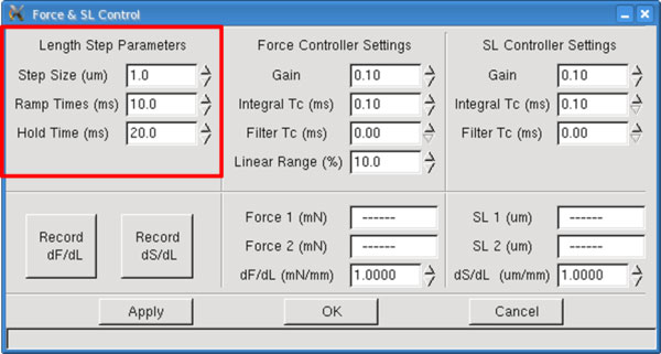
Fig 2. Length Step Parameters of the Force Control Panel
Set the Step Size for the length change that will be imposed during the stiffness measurement. The Step Size can be a positive (stretch) or a negative (shorten) value depending on the conditions under which you are measuring the stiffness. If the tissue is fully activated then you will not likely want to impose a further stretch on the tissue which would risk damaging the tissue. Under this circumstance it would be better to use a shortening movement. Likewise if you are measuring the passive stiffness then the fibre is likely near slack and a stretch movement is more appropriate.
It is better to start with a small value and observe the change in force resulting from that length change. Then incrementally increase the Step Size value observing the increased force change. Try to avoid length changes that result in very small force changes (changes that are only a few per cent of the full scale range of the force transducer) as there will be more error in the measurement. In general you want to produce force changes that are within the range seen during an experiment.
The Ramp Time variable determines the slope (time it takes to change the length by the Step Size) for both the initial length change and for returning the tissue back to the starting length. Ramp Time is measured in milliseconds (ms). Based on the type and size of the tissue you may want to vary the Ramp Time. Some tissues exhibit rapid force recovery after a length change and therefore, for these tissues, you may want to make the Ramp Time quite short. Likewise for larger preparations there may be a concern that a rapid stretch would damage the tissue so, in this case, a longer Ramp Time would be appropriate.
The Hold Time is the time that the length is held at the new length. Both length and force are measured before the Step Change and during the Hold Time. These measured changes in length and force are used to calculate stiffness. Some experimentation with Hold Time may be required to obtain the best measure of stiffness.
Ensure you use Scope to actually observe the behaviour of the length and force signals during the measurement as this behaviour will provide clues as to changes that may need to be made to Step Size, Ramp Time and Hold Time. Ensure that the changes in length don’t result in an overshoot or oscillation of the force during the period the force is being clamped or changed.
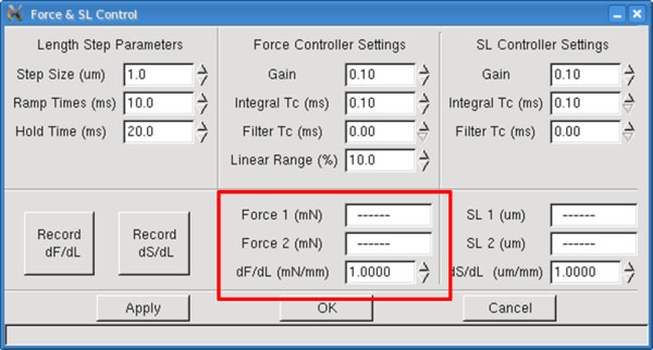
Fig 3. Force Measurements Are Populated Here Following a Length Step
Force 1 (mN) – Force 1 is the initial force recorded before the length change is made, it is measured in mN. This is a text readout box that shows the measured value, the user can’t change this text.
Force 2 (mN) – The force recorded after the length change is made, measured in mN. This is a text readout box that shows the measured value, the user can’t change this text.
dF/dL (mN/mm) – Calculated stiffness which is the force change per unit length change, expressed in units of mN/mm. This value can be overwritten by the user. If you have made a series of stiffness measurements at different force levels it is sometimes more convenient to simply enter the stiffness that corresponds to the conditions expected in the next protocol you intend to run.
There are four parameters used to tune the force feedback control. The parameters associated with the force controller are listed under the title Force Controller Settings and they are: Gain, Integral Tc (ms), Filter Tc (ms) and Linear Range (%).The control parameters depend on the model of length controller and force transducer being used, the tissue type and size, the tissue stiffness measurement, and the amount of tissue activation. Typically you will find that the control parameters will need to be adjusted for each different protocol you run. In practical terms this means that a protocol to generate a force clamp to 20% of the Fmax value and one to generate a force clamp to 80% of Fmax will need different values for the control parameters.
An added wrinkle for the determination of control parameters, is that you will also find that the individual control parameters affect each other. A change in one of the parameters will often require a change in one or all of the other parameters. Tuning the feedback control is an iterative process where you try a safe set of parameters, observe the results and then adjust the parameters to optimize the results. With time and experience you will find that the tuning becomes faster and easier and you will develop a “feel” for the correct values for the parameters.
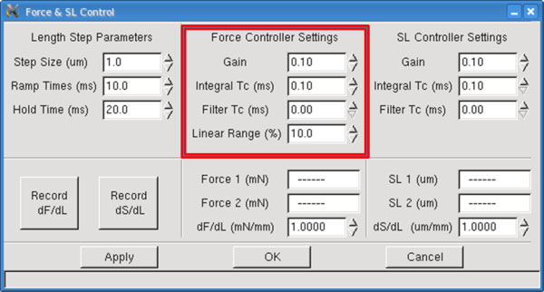
Fig 4. Force Control Parameters
Gain is the first parameter shown in the controller settings sections. The gain parameter in conjunction with the stiffness produces a corrective length control signal that is proportional to the current error between the actual force (SL) and the desired force (SL). The Gain parameter can vary from 0.0 to 1.0 but a safe starting value would be between 0.1 and 0.3.
Integral TC (ms) is the second parameter in the Force & SL Control window. Integral TC stands for the Integral Time Constant and it is used to eliminate small, steady-state errors in the controller. Without the integral term a small, constant difference between the measured force and the desired force would not be eliminated. The addition of an integrator has the disadvantage that it can slow the overall response and also introduce unwanted oscillations in the control signal.
Filter TC (ms) is the third parameter in the Force & SL Control window. Filter TC stands for the Filter Time Constant and it is used to stabilize the control output especially with noisy signals. Without the filter term the control signal will react to noise on the force signal. This reaction can result in major instabilities that make it all but impossible to obtain a force clamp. Since in the real world there is always noise on measurements it is imperative that the Filter TC value is always greater than 0.0. The addition of the filter on the control signal has the disadvantage that it can slow the overall response but this is more than overcome by its ability to stabilize the output.
The control parameter called Linear Range sets the threshold force. Linear Range is expressed as a percentage in the range from 0-100%. When Linear Range is set to 0% the stiffness varies linearly over the range from zero to Fmax. When Linear Range is set to 100% then the stiffness is constant over the full range of forces from zero to Fmax. The program uses the values Fref and Sref to calculate the slope of the stiffness curve. Fref is the Force 1 value measured when the stiffness was determined and Sref is the measured stiffness dF/dL. Initially set Linear Range to 100% and tune the rest of the force control parameters. Then try running protocols with force commands that control forces to different force levels and observe the results. If you find that the force control becomes unstable as the desired force increases then lower the Linear Range percentage. This will have the effect of increasing the stiffness at higher forces which should improve the stability of the force control.
Quick Step Guide for Setting Control Parameters
The following is a quick procedure that you can use when tuning force parameters.
1) Mount the tissue and make sure you accurately set the reference length, initial length and zero load.
2) Measure dF/dL with the tissue at resting tension. This will provide you with the lowest stiffness you can expect with this particular tissue.
3) If you are using a permeabilized tissue then fully activate the tissue in calcium and measure dF/dL again. This will provide you with the highest stiffness you can expect with this particular tissue. At this point you also want to set the Fmax value for your tissue which you should be able to get from the Scope screen when the fibre is fully activated.
4) Manually set the dF/dL value on the Force & SL Control window to a stiffness value between the two values measured.
5) Set Gain = 0.1, Integral TC (ms) = 0.5, Filter TC (ms) = 0.5 and run a protocol that includes the force control commands you wish to use during your experiment.
6) Observe the Length In and Force In signals using Analysis and zoom into where the force control action takes place. If the response is very slow then increase the Gain parameter and repeat the protocol. Continue to increase the Gain until the response is as fast as possible but still stable.
7) Lower the Integral TC value until you start to see overshoot and other instabilities occur then increase the value until these overshoot and instabilities are gone. Note: at this point you may need to go back and lower the Gain value since changes to Integral TC and Filter TC affect Gain.
8) Lower the Filter TC value until you start to see overshoot and other instabilities occur then increase the value until these overshoot and instabilities are gone. Note: at this point you may need to go back and lower the Gain value and possibly increase the Integral TC value since changes to Filter TC can affect both Integral TC and Gain.
9) Typically you will want the highest Gain and lowest Integral TC and Filter TC that results in fast, accurate and stable force control.
10) If your test will involve force control at different force levels (for example, force clamps to 30%, 20%, 10%, 5%, etc. of Fmax) then you should test the force control protocol at these forces and observe the results. If the force control becomes unstable at higher forces then lower the Linear Range % value and repeat the test. If you can’t keep the response stable at varying force levels by using the Linear Range control then you may need to use alternative values for Gain, Integral TC and Filter TC as the force level changes. However you may find that you can’t achieve the desired response with these parameters. If so then return these parameters to the values that you had after step (9) and alter the stiffness value shown on the Force & SL Control window. Changing the stiffness value is equivalent to making a major change to the Gain setting; be careful when changing the stiffness. From the range of stiffness you previously measured you may be able to make a reasonable guess of what the stiffness value should be as force varies. Please note that you may need to change Gain, Integral TC and Filter TC when you change the stiffness.
11) Once you have gained some experience with tuning the feedback control you will develop a “feel” for what you need to do to achieve optimal tuning. Often you will only need to make minor changes to the control parameters when you change tissue.
12) Remember that the overall gain value for the control equation is actually the Gain value divided by the stiffness value. Therefore if you have the wrong stiffness you won’t be able to properly tune the system regardless of the Gain value you set. Anytime you find you have a gain very close to either 0.0 or 1.0 this is an indication that the stiffness is not set correctly. Gain values close to 0.0 indicate the stiffness is too low whereas Gain values close to 1.0 indicate the stiffness is too high.
13) Integral TC is mostly affected by the model of length controller and force transducer you are using. Once you find an appropriate value for Integral TC it shouldn’t change that much (±0.1 or ±0.2) for different tissues.
14) Filter TC is mostly affected by the noise on the force transducer signal and therefore the value you need is strongly related to the actual force transducer you are using. Once you find an appropriate value for Filter TC it shouldn’t change that much (±0.1 or ±0.2) for different tissues. The most difficult control task is when you are trying to control force to values close to the zero. At this point even small noise on the force signal is large compared to the absolute force and you may need to increase Filter TC to obtain optimum results.
Measuring dS/dL:
The sarcomere feedback control works in a similar manner to the force feedback control.
Instead of stiffness we substitute dS/dL or the change in sarcomere spacing due to a change in tissue length. The units of dS/dL are um/mm, the change in sarcomere spacing measured in
microns divided by the change in tissue length measured in mm.
To determine dS/dL use the same method as outlined for determining dF/dL above. As with the stiffness measurement there will be a variability of dS/dL depending on the activation of the muscle tissue. Activated tissue can be expected to have a much higher value of dS/dL than non-activated tissue. As with the determination of stiffness select Step Size, Ramp Time and Hold Time to provide reasonable changes in length and in sarcomere spacing. We recommend using a Step Size in the range of 0.5-1.0% of the Initial Length (Lo).
Note: Ensure that the 901 HVSL 2 sarcomere length measurement system and the length controller are calibrated before determining dS/dL.
Once the length step parameters are set, click the Record dS/dL button. Three values will update, SL 1, SL 2, and dS/dL. It is recommended that you press the Record dS/dL button a few times to ensure the values remain consistent. A little deviation between measurements is normal and will not adversely affect the sarcomere length control function.
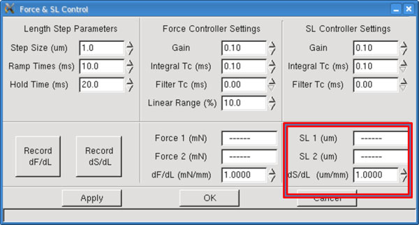
Fig 4. Measurements Are Populated Here Following a Length Step
SL 1 (um) – SL 1 is the initial sarcomere length recorded before the length change is made, it is measured in um. On the Force & SL Control window is a text readout box that shows the
measured value of SL 1, the user can’t change this text.
SL 2 (um) – SL 2 is the sarcomere length recorded after the length change is made, it is
measured in um. On the Force & SL Control window is a text readout box that shows the
measured value of SL 2, the user can’t change this text.
dS/dL (um/mm) – Calculated dS/dL which is the SL change per unit length change, expressed
in units of um/mm. This value can be overwritten by the user. If you have made a series of
dS/dL measurements at different activation levels it is sometimes more convenient to simply enter the dS/dL that corresponds to the conditions expected in the next protocol you intend to run.
The parameters associated with the sarcomere length controller are listed under the title SL Controller Settings and they are the same as the force controller parameters with the exception that there is no Linear Range (%) parameter. These control parameters are found in the top right sections of the Force & SL Control window. There are two distinct sets of parameters and even though they have the same names they are unique to the force and sarcomere length command functions used in protocols. If you place a sarcomere length command in a protocol then the program will use the Gain, Integral TC and Filter TC values found under the SL Controller Settings heading.
For further detail regarding the Force and SL control parameters and settings please refer to our 600A manual