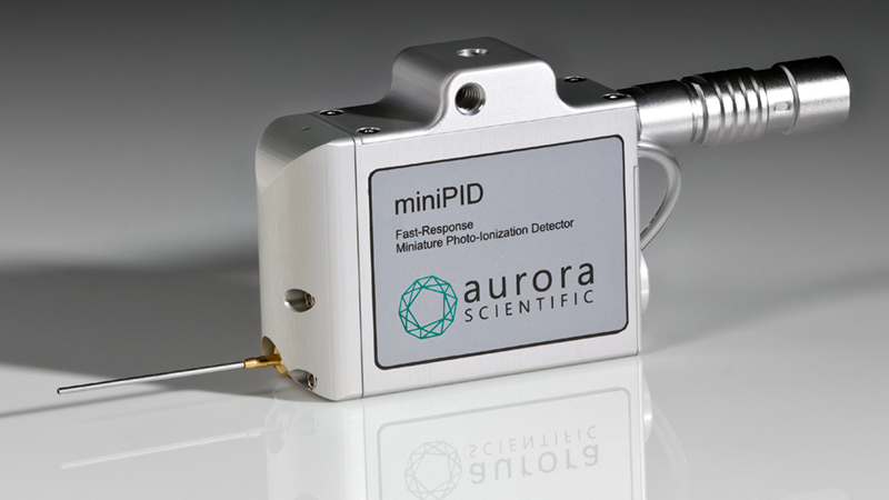
The 200B miniPID olfaction sensor was originally developed over 20 years ago as a fast response, analog sensor that was used primarily for wind tunnel dispersion applications. Since that time, the sensor has found a niche as an indispensable tool to validate the temporal properties of odour release from lab built and commercially available olfactometers, such as the Aurora Scientific 220A Olfactometer. As such, there are some useful tips and tricks that we should keep in our back pocket when using the PID to study olfaction.
How to manually light a stubborn UV Lamp
In a nutshell, the miniPID functions by lighting a UV lamp which directs the light through a small aperture that aligns with two high voltage electrodes. The odour is sucked into the PID through a small needle with the aid of a pump, where it is ionized by the UV light. The oppositely charged ions are attracted to the high voltage electrodes, where the change in charge is detected and is represented as a signal that is proportional to total concentration.
The UV lamp is unlike the incandescent or LED bulbs we have in our homes in that it does not have a physical connection to a voltage source to turn it on. These UV lamps are lit by an electric field which is created and adjusted by continuously ramping a high frequency waveform through a tightly wound coil around the lamp holder. Once the lamp is lit, this lighting process stops and the output of the lamp is held constant. The rate at which the lighting process occurs is fixed, so in certain instances (say when the lamp has not been lit in a long time, or it is nearing the end of life) it will not always catch and turn on with the auto lighting circuit.
A perfectly valid way of lighting the lamp manually exists. To do so, turn on the unit like normal, and then remove the circular cap which holds the lamp in the sensor head. You can then slowly pull the lamp partially in and out of the holder (see Figure 1) until it begins to glow violet. It may help to disconnect the suction line of the sensor head when doing this so there is no resistance keeping the lamp in place. Once the lamp lights simply replace the cap and use the unit as normal. We can light the lamp in this manual way as we alter the electric field around the lamp when we pull it in and out. Because the action of altering the field by hand occurs far more slowly than with the automatic circuit, we eliminate the lamp not turning on solidly.
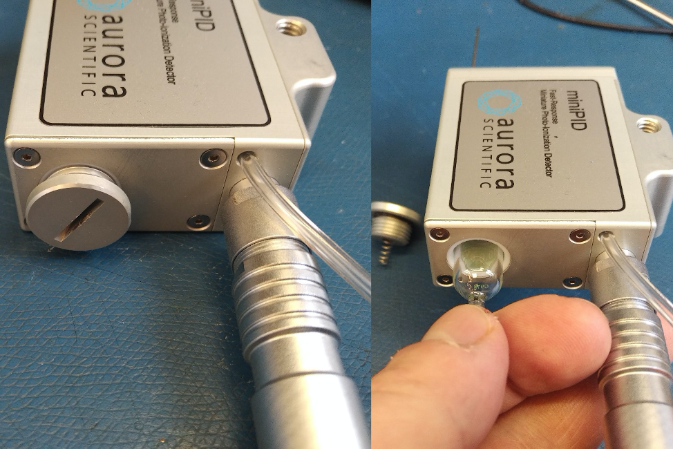
Figure 1: Removing the lamp holder’s cap and gently pulling the lamp partially in and out of its holder to lightThis is meant to be a means of ‘jumpstarting’ old lamps or those that haven’t been used in a while. In the event that the problem persists please contact Aurora Scientific as it may be indicative of a larger issue.
How to ensure a reliable output from your UV lamp and the PID itself
As was briefly mentioned earlier, the output of the PID unit is directly proportional to the amount of UV light which the lamp outputs at any given moment. The lighting control circuit of the lamp is meant to maintain the lamps brightness at a constant, reliable level each time the unit is turned on. However, this level can change over time and occasionally may need to be adjusted.
The UV lamps have a brightness profile that in many ways is like a narrow, Gaussian curve. Maintaining the lamp brightness at the peak of the curve is ideal for reliable PID measurements. To ensure that the output from the lamp is optimal, follow this procedure.
Turn on the unit and light the lamp using normal means, or the manual procedure discussed above. Once lit, remove the circular cap and turn down the ambient lights in the lab. Remove the lid of the control box and locate the lamp run potentiometer, labelled PT1 (See Figure 2). Using a small flathead screwdriver, you can adjust this potentiometer and observe whether the glowing of the lamp appears visibly brighter. Note that you should perform this adjustment slowly (perhaps ½ turns at a time) and always mark the starting position of the potentiometer in case that you need to start fresh. Also, if you observe any flickering (even if the lamp appears brighter) turn back the potentiometer to the point where no flicker is observed.
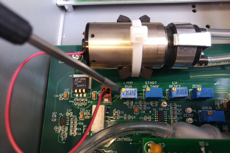
Figure 2: Adjusting the Lamp Run potentiometerThis adjustment process is not meant to be part of regular maintenance; however, it can be a useful diagnostic in certain situations. For example, if an abnormal level of baseline noise is detected, observing the lamp for signs of flickering and then adjusting its run voltage could be a potential solution. In the event of any persistent malfunction, please contact Aurora Scientific directly.
Adjusting the miniPID zero for the correct clean air reference
This final best practice tip for the miniPID is to ensure that the unit is properly calibrated for the clean air reference used in your olfactometer. All miniPID’s are calibrated at the factory with a bottle of zero clean air. Since the PID is only linear between 0-10V output, we set the output of the PID when connected to a flow of this zero clean air to 0.1V. This way, even in the event of some signal drift the output of the PID should theoretically never drift below this threshold, even with very dilute concentration outputs from the olfactometer.
However, the clean air supply that is used in your lab will not necessarily match what was calibrated at the factory. It is a good plan to reset the zero reference of the PID sensor for your own laboratory air supply as measurements of small concentrations may otherwise be affected.
The process to set this zero is quite straight forward. Turn the PID unit on like normal and connect the inlet needle of the PID directly to your clean air supply. Measure the output of the PID directly with a voltmeter or some similar tool. As with the lamp brightness adjustment we should open the miniPID controller and adjust the Zero potentiometer labelled R39 (see Figure 3). Just as is done at the factory we should ensure that the output of the PID is set to 0.1V. Also ensure that when this adjustment is being made the offset knob is centered at 5 on the miniPID control electronics.

Figure 3: Adjusting the zero potentiometer.Although it is good to use the cleanest air supply possible, as long as we have set the zero reference correctly in the PID, regular, filtered laboratory air will suffice. Keep in mind that you may need to re-zero your unit periodically depending on the use and especially if you notice your signal output appears negative. This is indicative of a high baseline which needs to be re-zeroed with clean air.