The combination of bubbling Ringers’ solution and electric current creates the perfect storm for corrosion. Although Aurora Scientific’s 1200A in-vitro test systems are made with corrosion resistant materials, the physical connections between the platinum field stimulation electrodes and the wiring are prone to oxidation and other corrosion.
How do you know if it’s a good time to replace your field stimulation electrodes? If you find that you are continously needing to increase the applied voltage/current for isolated muscle stimulation, it may be a good time. You can also check the resistance between the electrodes and the ends of the wires with an ohmeter. If the resistance is above about 1 or 2 ohms then it would be a good time to change them.
Finally, if your electrodes look anything like the set below, due to corrosion, it’s probably a good time to start thinking about replacements. Fortunately, replacement is not a difficult task, and if there are any doubts in your mind about the reliability of your field stimulation electrodes, you can always contact our engineers for advice.
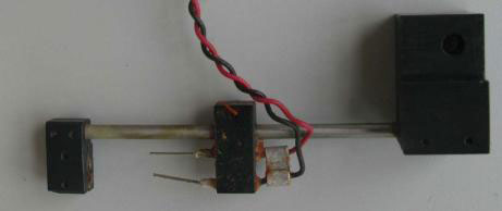
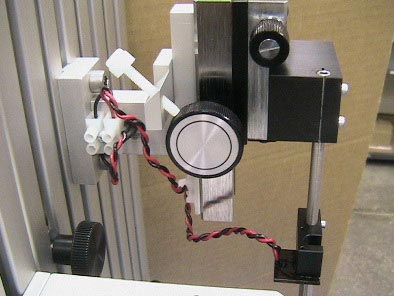
Figure 1: Corroded Field Stimulation Electrodes After Many Years of Service
To replace your electrodes the first task is to identify which version of the electrode holder you have. The original version (shown above) had electodes that fit directly into the holder. To replace them the lower tissue clamp (the leftmost block of Fig. 1) and the electrode holder (center block) will need to be removed. Loosen the screws holding the blocks to the post with an Allen wrench and then slide the blocks off the end of the metal post. Slide the replacement electrode holder onto the post and reattach the lower tissue clamp.
The second version of the electrode holder had the electrodes soldered directly to a circuit board. For this case you just need to remove the circuit board, you don’t need to remove the electrode holder or the lower tissue clamp. To replace the electrodes on this version, simply remove the circuit board by unscrewing the two screws holding the board to the electrode clamp.
At this point you will require a pair of wire cutters/strippers. Cut the red and black wires close to the old circuit board ensuring that you leave about 4 inches of wire attached to the BNC connector. Strip away about a 1/4” of insulation from the end of the cut wires.
Along with the replacement electrodes, ASI also provides a screw terminal block which you will mount away from the in vitro bath. This should help to minimize corrosion to the connections, provide an easy connection for the electrode wires, and facilitate future electrode replacements. Attach the terminal block with the provided tie wraps in the position shown below in figure 2.
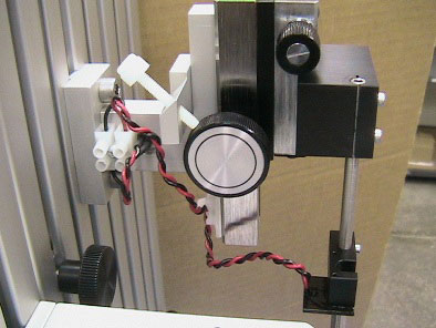
Figure 2: Terminal Block Placement & New Electrode Board
With the terminal block securely in place, connect the wires from the BNC connector to one side of the terminal block. Place the stripped ends into the holes as shown above and with a flat head screwdriver tighten down the contacts.
Proceed to attach the new electrode board to the electrode clamp with the two #1-72 screws removed initially. If the electrodes were of the original design, a new electrode clamp will be provided. Slide it onto the stainless steel support tube as shown in figure 2. The screws for mounting the electrode board to the clamp will also be provided.
Once the new electrodes are secured in place, the wires from the electrode board may be attached to the terminal block. Make sure that the colour of wires matches on both sides of the terminal block – red to red, black to black. The stripped ends of the wires should be placed in the holes in the terminal block and clamped down with a flat head screwdriver as before.
Finally, just to clean up, remove the backing paper from the provided tie wrap base, and stick it to the rear of the positioning stage as shown in figure 2. Tie wrap the wires to keep them neatly out of the way of your experiment.
The electrode conversion is complete. You are now ready to resume your isolated muscle stimulation experiments with your 1200A in-vitro test system.
Stay tuned to the blog for more ‘how to’s’ and technical support documents!
Thanks for your support; we’d love to hear more from you.