One of the most common misconceptions when it comes to using our 300C-I Dual Mode Indenter, is that instructing a force profile in software via the Force In channel, will result in the device instantaneously eliciting a response and some sort of movement profile. This blog is meant to explain why this is not the case and serve as a guide to performing quality force control experiments.
The motor assembly of the Dual-Mode Indenter is a moving coil galvanometer. The amount of electrical current flowing through this coil is proportional to the load, or force. This force can be measured by the lever system, but can also be controlled, while instead simultaneously measuring the displacement. Thus, if there is no load to control, there will be no movement or displacement.
We can use the Force Offset dial on the front panel of the controller to set the amount of current which can flow through the coil contained in the motor itself. The dial therefore acts as a force limiter for the motor. This can be observed by gently touching the indenter probe with your forefinger while it is attached to the motor shaft. You will notice the difference in the amount of resistance from the probe as you turn the Force Offset Dial fully counterclockwise from 10 to 0.10 in this case 10 being the maximum holding current (and hence the stiffest) and 0 being no holding current (and hence the limpest). The indenter probe will begin to move once your forefinger overcomes the set resistance. In this way, when the probe is moved by your forefinger, the resistance remains the same, (thus force is controlled) and displacement can be measured.
This force offset knob is useful for a static test such as above, but it would be impossible to set any sort of dynamic force control profiles with it alone. Setting a force profile using a software tool would be much more powerful. This can be accomplished by sending a voltage waveform to the Force In BNC, which is proportional to the desired instantaneous resistance.
In order to properly execute a force control experiment we should follow this procedure.
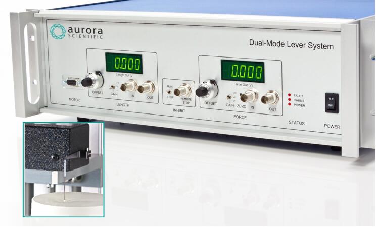
- Firstly, turn the force offset knob on the controller of your 300C-I Dual Mode Indenter to 0. (See figure 1) We must perform this step as both the contribution from the Force In BNC and the Force Offset Dial are additive. Thus, any contribution from the knob will make the commanded force seem higher.

Figure 1: Force offset control knob set to zero.
A note of caution. Sometimes, when researchers have the Force Offset Dial turned all the way down to 0 and flick the switch from ‘Inhibit’ to ‘Run’, they see a kick in the lever arm and notice that the fault LED illuminates on the controller. If the force offset knob is turned down all the way to 0 and no nominal holding resistance from the software, the weight of the indenter arm itself can rotate the shaft of the motor out of range and thus trigger a fault. In order to ensure that this does not occur, either briefly turn the Force Offset Dial up pre-experiment, or use your DAQ/software to supply some holding force signal until you are ready to begin the experiment.
- In order for the lever system to perform the force control experiment you must initiate contact with the surface of interest with the tip of the indenter probe pre-experiment. (Figure 2.) You can do this manually – i.e. using a micro positioner on whatever type of apparatus you have the motor mounted on to get the indenter arm as close as possible to the experimental surface. When very close to making contact, feel free to use the ‘Length Offset Dial’ to change the angular position of the lever arm while keeping an eye on the ‘Force In’ display on the controller of the 300C-I. Once you see the values on this start to increase, you know that the tip of your probe is now in contact with the sample. You can also do this by commanding a length movement by voltage to ‘Length In’. When you make contact with the sample you need to make sure your baseline length is more than 0V as length control occurs only in the positive voltage regime.

Figure 2: Indenter probe shown making good contact with compliant material
-
- A useful ‘pre-experiment’ technique to determine if there is adequate contact between both the indenter probe and the surface to induce the force of interest is to perform incremental increases in the ‘Force In’ channel of the software. If you notice that after a certain ‘Force In’ delivery that the max force begins to plateau, or is not as high as expected, you need to increase the ‘pre-experiment contact’ between both the probe and the surface of interest. Note that very little contact is required if the commanded force is low, but must be increased if controlling to large forces. This step mostly need only be taken if the tip is just brushing the surface. The device may be used in any orientation but for best results, we would recommend using our indenter probe and tips in a 90 degree, directly downward motion. Applying the tip at an angle, or extending the probe much beyond the stock length can result in issues with reliable force control.
- Once you have the probe in the correct position, adequate contact between the probe and the surface to induce the forces of interest, and your protocols are optimized – you are more or less ready to proceed with your experiment as planned. It is important to note the scaling factor of the device. After calibrating your device, you should be aware of the amount of force per volt which you are commanding from the software. If you notice that the scaling factor is not as expected, please verify that your gain switch on the face of your controller is at x1 and also check whether there is some gain setting from the software or DAQ system.
Please contact us directly with any questions or stay tuned to the blog for any future tips and tricks!