One of the most useful facets of Aurora Scientific’s Dynamic Muscle Control (DMC) software is the ability to use reference units for force and length. These allow the user to set general experimental protocols that can be re-used without having to recalculate parameters for each individual tissue. It also allows the user to calculate multiple parameters automatically, saving time and effort. For example, we would like an eccentric contraction protocol that includes a stretch of 10% of the initial length (Lo) of the muscle. Instead of calculating 10% of Lo for each individual muscle sample, the Lo of the muscle is inserted into the software as a reference unit, and the 10% stretch will be calculated automatically during the protocol.
Switching “Length In/Out” channels to reference units
Generally length reference units will be used when you want to control length and measure force. Eccentric or concentric contractions would be a good example of when this would be required.
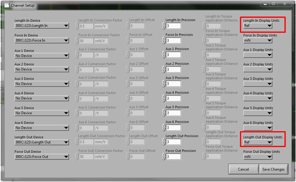
First of all the DMC software must be told to change the channel for “Length out/in” from absolute units (mm, cm etc.), to a reference unit (in this case Lo). To do this you must click on the “Setup” tab and select “Channel Setup”. A new window will pop up as shown in Fig.1. This window allows you to change the units displayed for all your channels, including Length in/out. Click the arrow underneath “Length In Display” or “Length Out Display” to show a drop-down menu with all the units available for the respective channels. Select “Ref” on both of these to change the units for Length to units of Lo.

Fig. 1 The “Channel Setup” window with the channels for “Length Out/In” highlighted.
Now that the unit for length has been changed to Lo, the Ref Length box seen on the main DMC screen is available for editing. For this example let us presume we have a muscle that has an initial length of 20 mm. The number “20” would be input into the “Ref Length” box as shown in Fig. 2. Now the DMC software assumes 1 Lo is equal to 20 mm. The offset Length box on the main DMC screen controls the initial position of the lever arm. In most cases the lever arm will be set to its centre position and this box will be kept at 0 as shown in Fig. 2.
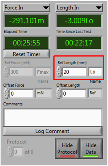
Fig. 2 Changing the value for reference length.
Writing protocols using Length in/out reference units
After inputting our value for the initial length of the muscle, the next step is to write a protocol to take advantage of our reference units. Let us take the example of an eccentric contraction with a stretch of 10% of the Lo. To open the protocol editor click the “Protocol” tab. As we are using reference units, the first thing to change is the unit settings on the top right of the protocol editor. In this case we should be using Muscle %.
As shown in Fig. 3, the example protocol contains a simple tetanus stimulation with a 10% Lo stretch, followed by a return to Lo. Commands to change length are read as a movement to a particular value, rather than relative movement. Therefore, the 10% increase is achieved by entering “0.1” into the box marked “Parameter”. A value of “0.5” would be put in for a stretch of 50%, “0.6” for 60% and so on. The return to Lo is achieved by entering “0” into the parameter box, which commands the motor to return to the initial position.
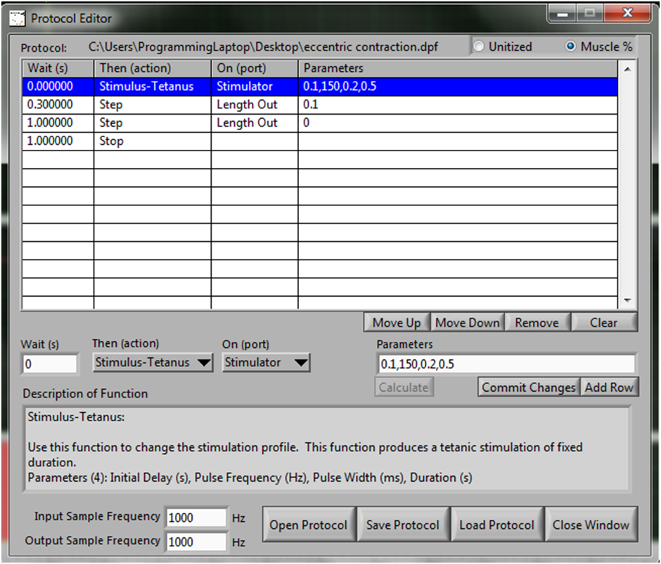
Fig 3. Protocol for an eccentric contraction with a 10% Lo stretch
Switching the Length channels to reference units also changes the display of graphs in the main window of DMC. Shown below is the 10% stretch protocol that we discussed above, viewed in the DMC window. Although the units on the graph axis are expressed in reference units in the main screen (Fmax and Lo), protocols in the graphs are always expressed in absolute units (mN and mm etc.). This is so you can check what your protocol is going to do in absolute units, to ensure that you do not damage the muscle by overstretching. So in this example, 10% of Lo (10% of 20 mm) is equal to 2 mm (Fig. 4), and this shows as a red line signifying your protocol. When data is recorded, however, it is displayed in reference units. So in this example the movement of the lever arm would be recorded and displayed on the DMC screen in green as 0.1 Lo rather than 2 mm.
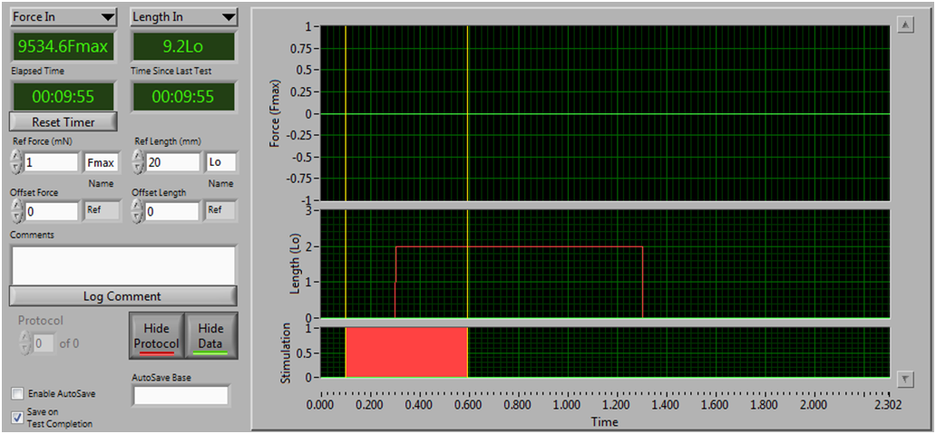
Fig 4. An eccentric contraction with a 10% Lo stretch displayed on DMC
The second example protocol contains a 10% Lo slackening instead of a stretch (Fig. 5). In this case, the lever arm must move to a negative position, therefore, “-0.1” is entered into the parameter box. Again, the return to Lo is performed by entering “0” into the parameters box, as the motor responds to absolute values rather than inputting relative movement such as “+0.1”.
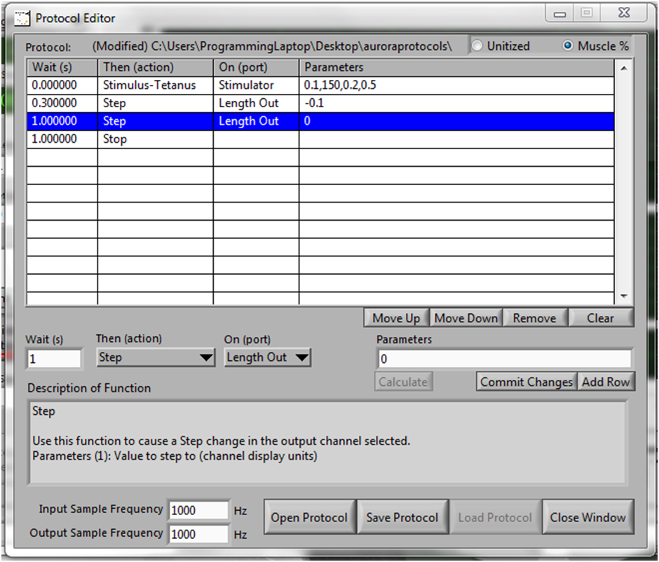
Fig 5. Protocol for a concentric contraction with a shortening of 10% Lo.
Now you are ready to use reference units for length to run your protocols. Please check out some of our other blog posts on how to get the most out of your ASI software and hardware.
Optimizing muscle resting length (Lo) with DMC software
Establishing optimal stimulation conditions in intact muscle