The procedure for replacing a broken output tube involves removing the broken tube and the glue used to hold it in place and then gluing a new tube in its place. The most critical step of the procedure is removing the broken tube and glue. It is during this step that there is the greatest chance of breaking the force transducer flexure.
Field replacement of the output tube has been a problem in the past since the new tube must be accurately positioned so that it exits through the centre of the small hole in the transducer cover plate. The precision-machined alignment jig, included in the repair kit, solves this problem by holding the tube perpendicular to the flexure and positioning it in the correct location while it is being glued. The jig ensures that the new tube will exit through the centre of the hole in the cover plate when reassembled.
The toolkit includes several Allen keys required to remove the screws that hold the transducer cover plate onto the main body. The size of key depends on when your transducer was built. To determine what size of key you should use for your transducer please consult the 400-TR instruction manual included along with your kit.
In addition to the tools included in the 400-TR kit you will also need:
1) A short length (about 2” (5 cm)) of wire about 0.020 – 0.030” diameter to be used to place the epoxy glue around the new output tube (you could also use a tooth pick as a substitute).
2) A small piece of cardboard to mix the epoxy on.
3) A mixing tool such as a Popsicle stick or a blade screwdriver to mix the epoxy.
CAUTION: Avoid touching the output tube with your finger. Although the unit can withstand sever overload and is very rugged, it is possible to overlook how easy it is to develop relatively high forces manually.
Unplug the transducer head from the electronics. Remove the transducer head from the experimental set up and place it on a clean workbench.
Remove the socket head caps screws holding the cover plate in place. Remove the screw at the end of the housing closest to the output tube last.
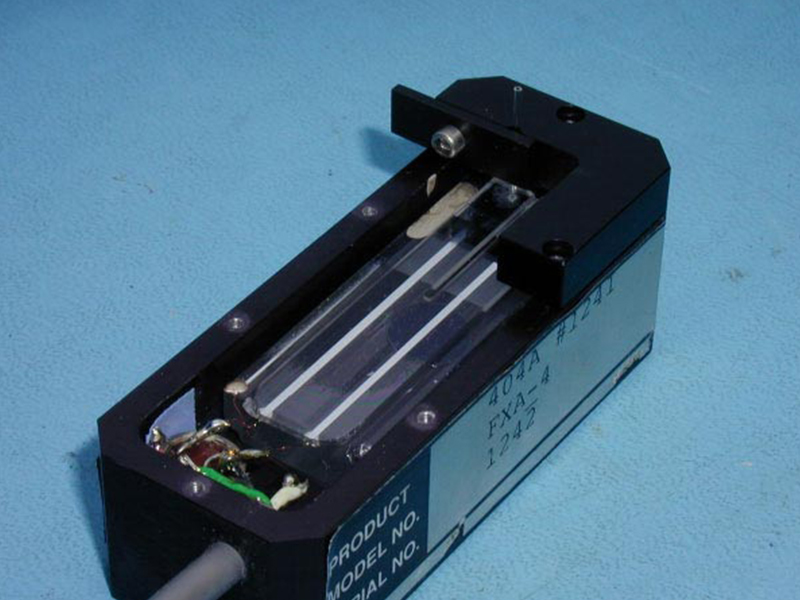
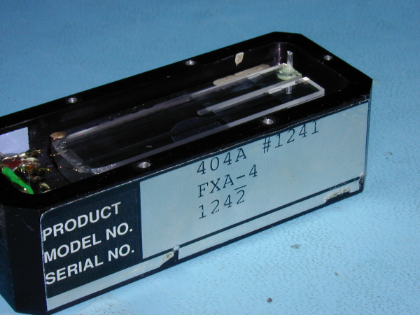
Carefully remove the cover plate by lifting it straight up until it clears the broken output tube. Failure to remove the cover plate carefully can cause sever side loads on the remaining piece of output tube. These loads can result in the flexure breaking. The transducer head should look similar to Photograph 1.
Photograph 1 Transducer Head with Cover Removed Showing a Broken Output Tube
Unpack the butane-powered hot air torch. The torch is shipped with the Heat Blower Tip attached. This is the tubular tip with what looks like a small piece of screen in the end of the tip. The torch comes filled with butane fuel and refilling cans can be purchased at most hardware stores. Make sure that the torch has cooled completely before refilling.
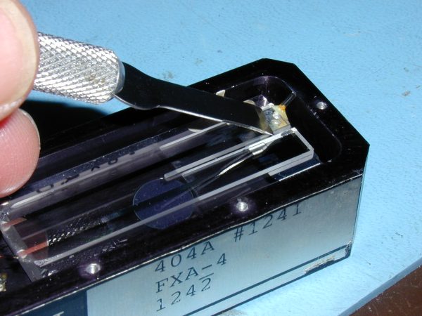
Light the torch. Ensure that the gas control valve (on/off adjuster) is in the low to mid position. Do not use the soldering iron on maximum heat because you can damage the metallization on the glass flexure assembly. Direct the hot air towards the chisel blade of the X-Acto knife to heat it up sufficiently. You may need to let the hot air blower heat the blade for a minute or two before proceeding. Once the blade is sufficiently hot, use the X-Acto blade to scrape away the glue spot. This should be done in one smooth movement with the blade at a 45 degree angle. If you encounter resistance when scraping, stop and reheat the blade some more. Under no circumstances should you direct the heat straight down onto the flexure or towards the wire end of the flexure. See Photograph 2. Take special care. This step is the most critical one of the entire procedure and the most likely place where you can break the flexure.
Do not apply excessive pressure with the knife blade. If the blade is hot enough then the blade will gently slide along the glass flexure and under the glue joint lifting the glue off of the glass. If the glue does not come off easily then heat the blade longer. Watch the flexure as you are sliding the knife, if the flexure starts to rise up then stop moving the knife. Likewise if you see the flexure bend down and push against the substrate then release the pressure on the knife. Under no circumstances should you apply lifting force to the glue. Slide the knife along the flexure and allow the chisel shape of the knife blade to lift the glue up.
Photograph 2 Removing the Old Glue
Once the glue has been removed inspect the surface of the flexure and use the knife along with the heat gun to remove any glue residue. If available use a cotton-tipped applicator moistened with methanol to gently clean the surface of the flexure. Note: do not apply methanol to a hot flexure, allow the assembly to cool before applying the cleaner fluid. Blow any dust or glue particles off of the glass assembly (using Dust-Off or a similar canned air supply). Be careful not to use excessive air pressure since the force of the air exiting an air can is sufficient to break the glass flexure. With models 403A, 405A and 406A it is recommended that you place your finger lightly on the flexure about mid-way along the flexure before blowing the end of the flexure with the canned air. Your finger prevents the flexure from rising up due to the air pressure and breaking.
Attach the tube alignment jig to the force transducer head with the cover plate screws as shown in Photograph 3. Loosen the output tube clamp screw on the alignment jig and insert a new output tube into the “V” groove. Allow the tube to drop gently onto the flexure. Do not push down on the tube with your finger. Inspect the tube and ensure that the tube is in contact with the flexure.
Gently tighten the output tube clamp screw to clamp the output tube to the alignment jig. Mix a small amount of epoxy. Squeeze equal portions of resin and hardener onto a small piece of cardboard. Then, using a mixing tool, thoroughly mix the epoxy together. Note you should mix for at least 1 minute. The epoxy cures in 5 minutes so ensure that you are ready to glue before mixing the glue. Take care not to get any epoxy on your skin.
Photograph 3 Tube Alignment Jig Attached to Transducer Head and with a Tube in the Clamp
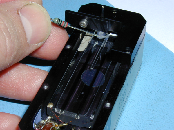
Using a short length of wire (about 2” (5 cm)) apply a small amount of epoxy to the base of the output tube. See Photograph 4. Using the wire distribute the epoxy around the base of the output tube. Take care not to get any epoxy down the sides of the flexure or on the small gap between the two flexure arms. Any epoxy in these areas can glue the flexure to the substrate thus rendering the transducer useless. Note very fine strands of epoxy will often form between the applicator wire and deposited epoxy. These strands of glue can fall down the sides of the flexure and glue the flexure to the substrate. Consequently remove the wire from the deposited epoxy slowly thus allowing time for these strands to break before they get long enough to cause problems.
An alternate approach to applying the glue is to loosen the tube clamp and raise the tube above the surface of the flexure. Then apply a small amount of epoxy directly to the flexure immediately below the output tube. Now lower the tube into the glue and gently rotate the tube about its axis. You may then lift the tube about 1 mm off of the surface of the flexure and then lower the tube back into place. The rotation and lifting actions help to distribute the glue around the tube. Ensure that when you lower the tube into the glue that you do not use excessive pressure since you can easily overload the transducer by applying force with your finger. Tighten the tube clamp and allow the glue to harden.
Photograph 4 Applying the Epoxy Glue
Allow the epoxy to harden for at least 30 minutes, we recommend 1 – 2 hours. Carefully remove the output tube clamp screw and the clamp plate from the alignment jig and thenremove the two screws holding the alignment jig to the transducer head. Slide the jig away from the output tube.Replace the transducer cover. Carefully hold the cover parallel to the transducer head and sight through the output tube hole in the cover. Align the output tube with the hole and gently lower the cover in place. Re-attach the cover using the cover screws. Insert the screw at the end of the transducer head closest to the output tube first. Then insert the screw on the opposite end of the head. Align the cover so that the tube exits from the centre of the hole and tighten the six screws. If the cover cannot be replaced without the tube touching the edge of the hole then the alignment jig was not attached properly. Remove the new output tube and the glue as explained above and then re-glue a new tube.
Congratulations, you have successfully completed an output tube repair for your Aurora Scientific 400A series transducer. Please stay tuned to the blog for more tips and tricks or email us to request a blog topic!

