This blog is intended to navigate you through the process of calibrating your 300C Dual-Mode Muscle Lever Series using Dynamic Muscle Control (DMC). A proper calibration of your lever system is essential to obtain precise and reliable data and is part of good experimental practice. Calibration does not need to be performed daily, but should be part of the procedure before beginning any study with the Dual-Mode Lever System.
Accessing the Calibration Editor
The Calibration Editor can be opened through the My Instruments option which is located in the Setup menu tab. To calibrate any of your instruments, use the scrolling arrow to the top left of the saved lever system models in the My Instruments window to choose the desired unit. Then click the button labelled ‘Calibrate’ which will be to the right of desired model. This will open the Calibration Editor window where you are able to calibrate Length, Force In and Force Out.
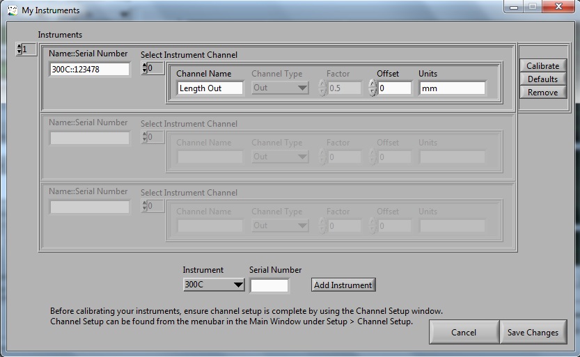
Figure 1. 610A Dynamic Muscle Control (DMC) software screen shot depicting the My Instruments window.
Calibrating Length
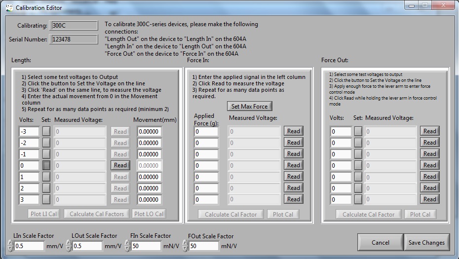
The length function is calibrated using the box to the far left in the Calibration Editor labelled ‘Length’. This calibrates both Length In (length change measured by instrument) and Length Out (length movement command signal). To calibrate these signals we must first deliver a known output voltage to the lever system through the software and then we physically measure the length change of the lever arm. The lever system is closed loop, thus the calibration editor records the position feedback signal for the lever system in volts.
To begin with the length calibration pick a series of test voltages. Seven points can be measured and stored and they may range from -10 volts to positive 10 volts. It is recommended to calibrate in both the positive and negative directions with the center at 0 volts. Pictured below is an example length calibration from -3 to +3 Volts.
Once these voltages have been entered, the next step is to click the ‘Set’ button for the first line. The software will produce the desired voltage (in the case of the photo -3 volts) which causes the lever arm to move. Next, click “Read” on the same row. This reads the actual voltage from the lever system from its length out port. You must also measure the exact movement of the lever arm in millimeters (see below for a suggestion), enter it into the corresponding box and continue on to the next voltage. Once all voltages have been recorded, you can click the Calculate Cal Factors button. This will be recorded in mm/volt.
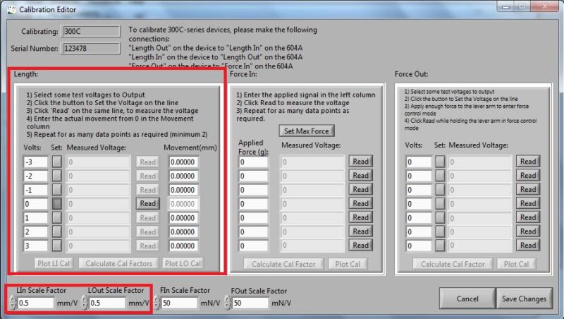
Figure 2. DMC software screen shot showing the Calibration Editor window. (Length channel calibration and scale factors boxed in red).
Measuring the Length Change of the Lever Arm
To perform an accurate length measurement, we need a high degree of precision to make calibration worthwhile. This is why we suggest the following method using Vernier calipers.
First, ensure your analog length setting is set to 5 on the control box. Detach your motor from your apparatus and place it on the side of a table with the lever arm pointing vertically down over the edge of the table. Next, take some electrical or masking tape and stick it across the table’s edge so that it is in line with hole at the end of the lever arm. The lever arm should be pointing down vertically so that 0 volts corresponds to the center position. To mark the different lever arm positions on the electric tape for each voltage that you set, use a thin gauge pin or needle. Push the pin through the hole in the end of the lever arm into the electric tape to make a mark at each set voltage change. Remember, you are measuring the distance between the 0V mark and the each of the 6 other voltages individually so start off by marking the 0V position and continue from there. The distances can be measured in mm with a set of calipers.
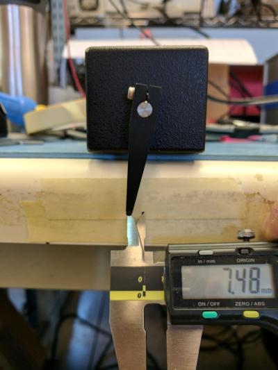
Figure 3. Length calibration of 305C, lever arm movement measured with Vernier calipers.
Calibrating Force In
To calibrate Force In you will need a set of known weights. We recommend that these are increasing in a linear progression between the range of 0-50% of the max force measured by your lever system.
Before you begin click the “Set Max Force” button above the Force In calibration window in the calibration editor to set the maximal holding force of the motor. If you have the manual force offset knob on the lever system control box already set to 10, you can disregard this step.
Next, position the motor so that it is on the edge of a table or platform and the lever arm is horizontal and sticking over the edge to provide adequate clearance for your weight to hang. Please note that you must hang the weight with a compliant link between the weight and the lever arm, such as an elastic band. You may choose to thread a string through the hole in the lever arm and make a 2nd loop with the elastic band.
When ready, hang the first weight from the elastic band and enter the value of the hanging weight in grams into the “Applied Force” box on the first line. Be certain to account for the mass of the elastic band. When the mass has stopped swinging click the read button. This will read the voltage from the lever system that correspons to this applied load. Do this for at least 3 different weights up to a maximum of seven. Once completed press Calculate Cal Factor to calculate. The calibration data and curve fit can also be plotted by clicking on the Plot Cal button for verification.
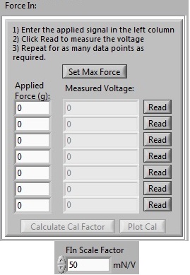
Figure 4. Force In calibration window and scale factor.
Calibrating Force Out
Before calibrating the Force Out signal, make sure that the Force In signal has been properly calibrated first.
The text boxes shown in the “Volts” column are used to send output voltages through the Force Out port to the lever system to alter the maximum holding force of the motor. We would recommend setting the calibration values to be equally spaced throughout the anticipated force range. In this case it is very difficult to use 0 volts as a data point as this would mean no holding force for the lever system. Also, remember that before beginning this calibration, the force offset knob on the lever system box must be set fully counter clockwise at 0.
Enter your seven calibration voltages into each box up to a maximum of 10 volts. To calibrate each line, you will click the “Set” button next to the calibration voltage. This sets the Force out signal to the corresponding calibration voltage that you have put in that line’s text box.
Now, using your finger, you need to apply enough force to the lever arm to place the lever system in force-control mode. This means that the lever system will automatically move to maintain the set level of force being applied to the lever arm. To do this, gently apply increasing pressure to the lever arm until the Force Out display reading stops changing and you can feel the arm starting to move. Hold the arm in this position with your finger and then click “Read” on the corresponding row. This causes 100ms of data to be collected from the lever system at which point an average voltage is calculated by the software. The result is shown in the “Measured Voltage” text box. Repeat this for all 7 lines and when completed click the Calculate Cal Factor button.
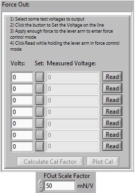
Figure 5. Force Out calibration window and scale factor.
At this point, your instrument is fully calibrated and is ready for experimental use! Be sure to remember to click the ‘save changes’ button in the bottom right corner to make certain the calibration is remembered by the software.
For any other questions about calibration or other support topics please contact Aurora Scientific directly.If you’d like more tips on how to use 615A Dynamic Muscle Control and Analysis Software or what our 300C Dual-Mode Muscle Levers can do, check out some of our previous blog posts!
How to Write Basic Protocols in DMC – Isometric
How to Write Basic Protocols in DMC – Concentric and Eccentric