ASI’s 600A Digital Controller provides a quick and easy-to-use module for calibrating your instruments and storing the resulting calibration files for use in your experiments. It is best practice that you perform a proper calibration of your length controller and force transducer post shipping and routinely thereafter.
The Calibrate menu contains commands to set the models of length controller and force transducer that will be used with the 600A controller. It also allows you to calibrate both length and force and to provide force and sarcomere length feedback control.
Length Calibration
The Calibrate→ Length menu item opens the Length Calibration window. This window provides a simple means of calibrating the length channel input and output. The calibration screen can be used to perform multipoint calibrations or you can simply enter a known calibration constant.
To calibrate a lever system you will require an independent means of measuring the length (or position change) of the lever arm. A ruler or a microscope reticule with appropriate increments can be used. It is advised that you remove the lever system from the apparatus which it is attached to and fix it to a stable surface where it is easy to measure the movement of the lever arm.
At the start of calibration you will note that there is a Length In value next to the 0.00 value under the Length Out (v) column while all other boxes in the Length In (v) column are blank. Upon entering the Length Calibration screen the program sets Length Out to 0.000 V and records Length In. This value is then displayed in the Length In column. Now set the Length Out voltages to your desired values or use the default values shown. Use the up/down arrows to the right of the Length Out (v) column to set the length out voltage or simply type in the desired voltage in the text box. Pressing the radio button to the left of the desired Length Out (v) setting will send that voltage to the length controller and will also cause the 600A software to measure the current length input.
After each voltage output, manually measure the actual length and then enter this length in the column labeled Length (mm). Repeat this procedure for up to five Length Out voltages. Once complete press the Calculate button at the bottom of the screen. The program will plot the calibration data, fit a curve to the data and then automatically calculate Length Out and Length In Scale factors and Offsets. Alternatively, if you know the input and output scale factors and offsets you can enter them directly in the text boxes on the right side of the screen.

Fig 1. Length Calibration Window on 600A Digital Controller
Force Calibration
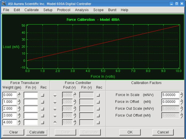
The Calibrate → Force menu item opens the Force Calibration window. This window provides a simple means of calibrating the force. The calibration screen can be used to perform multipoint calibrations or you can simply enter a known calibration constant.
To calibrate the force transducer you will require a series of known masses that can be attached to the force transducer. It is useful to hang the weights from an elastic band or suture which is attached to the hook or the pin attached to the output tube. Ensure that the mass of the weight you are attaching does not exceed the maximum force range of the transducer that is being calibrated.
Start with no mass attached to the transducer and press the square radio button in the Rec column next to the 0.0gm line. Pressing the radio button causes the program to measure the current Force in signal. Now apply a series of known weights to the force transducer, enter the actual weight and press the corresponding radio button. Repeat this procedure for up to five weights. Once complete, press the Calculate button at the bottom of the screen. The program will automatically calculate the Force In Scale factor and the Offset.
If you are calibrating a dual-mode lever system then the Force Controller information will be un-greyed and a calibration of the control signals can also be performed. Alternatively, if you know the input scale factor and offset for your transducer you can enter them directly in the text boxes on the right side of the screen.

Fig 2. Force Calibration Window on 600A Digital Controller
If you intend to use force control or SL control in your experiment you will need to setup the Force and SL control parameters before starting each experiment. This is done through the Force and SL control window. Please see the upcoming post on setting up these parameters on the Force and SL control window in 600A.